TP-6073 4/06
57
Section 9 Generator Disassembly/Reassembly
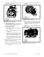
21. Install a sling on the stator housing.
See
Figure 9-7.
22. Use a two-jaw puller to pull the end bracket/stator
assembly from the bearing on the rotor shaft. See
Figure 9-7.
558867
1
1. Sling
2. Fan guard
3. Two-jaw puller
4. End bracket
4
2
3
Figure 9-7
Stator Assembly Removal
23. Remove the stator assembly from the rotor.
Remove or rotate the fan guard, if necessary, to
clear the vibromounts.
24. Remove the eight fan bolts and remove the fan and
fan spacer. See Figure 9-8.
25. Remove the eight drive disc bolts to remove the
drive disc/rotor assembly from the engine flywheel.
See Figure 9-8.
26. Clamp the rotor in a soft-jaw vise. Remove the eight
bolts and remove the drive disc assembly from the
rotor. See Figure 9-9.
558868
1
3
1. Fan
2. Drive disc/rotor bolts
3. Fan bolts
4. Rotor assembly
2
4
Figure 9-8
Disc/Rotor and Fan Assembly
5588610
1
2
3
1. Drive disc
2. Rotor
3. Bolt
Figure 9-9
Drive Disc
Summary of Contents for 10EOR
Page 10: ...10 Safety Precautions and Instructions TP 6073 4 06 Notes...
Page 12: ...TP 6073 4 06 12 Service Assistance Notes...
Page 22: ...TP 6073 4 06 22 Section 3 Intake and Exhaust System Notes...
Page 26: ...TP 6073 4 06 26 Section 4 Fuel System Notes...
Page 30: ...TP 6073 4 06 30 Section 5 Cooling System Notes...
Page 38: ...TP 6073 4 06 38 Section 6 Controller Troubleshooting Notes...
Page 54: ...TP 6073 4 06 54 Section 8 Component Troubleshooting Notes...
Page 60: ...TP 6073 4 06 60 Section 9 Generator Disassembly Reassembly Notes...
Page 82: ...TP 6073 4 06 82...
Page 83: ...TP 6073 4 06 83...


