TP-6073 4/06
31
Section 6 Controller Troubleshooting
Section 6 Controller Troubleshooting
6.1 Controller Sequence of
Operation
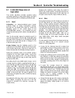
This section describes controller operation during
generator set starting, running, and stopping. Use these
data as starting points for identifying controller faults.
6.1.1
Start
Preheating.
An
intake-manifold-mounted
heater
preheats intake air during cold-weather starting.
Energize the air heater (AH) relay by rocking the
start/stop
switch
on
the
control
panel
to
the
STOP/PREHEAT position.
The energized AH relay
closes the normally open AH contacts, energizing the air
heater.
After 15--20 seconds, release the start/stop switch to
open the ground path to the AH relay, deenergizing the
AH relay and the air heater. Do not energize the preheat
feature for more than 30 seconds or damage to the
preheat feature may occur.
Engine Startup.
Rock the start/stop switch on the
control panel to the START position to start the engine.
If the engine doesn’t start, check the 10-amp fuse. A
blown fuse prevents the following starting sequence.
Setting the start/stop switch to the START position
energizes the K2 relay (LED2 lights), closing the
normally open contacts of K2. The closed K2 relay
contacts energize the K3 relay, the K25 relay, and the
fuel pump motor (FP).
Energizing the K3 relay (LED3 lights) closes a set of
normally open K3 contacts, energizing the K20 relay. A
set of normally open K20 contacts close to energize the
starter relay (SR), causing the normally open SR
contacts to close. The closed SR contacts energize the
starter motor (SM). The starter motor gear engages the
ring gear on the engine flywheel to begin cranking the
engine. At the same time, the power supplied to the
starter motor energizes the pull-in coil of the fuel supply
solenoid (FS).
Energizing the K25 relay closes a set of normally open
K25 contacts, energizing the hold coil of the fuel
solenoid to complete the conditions necessary for
engine startup.
Releasing the start/stop switch allows the switch to
return to its neutral position. If the start/stop switch is
released before the engine starts, the K1 relay does not
energize, which stops the engine startup sequence.
6.1.2
Run
During engine startup, a set of normally open contacts of
the K2 relay (which are closed during startup), two
diodes, and two normally closed K1 contacts provide
flashing current to the generator field. The combination
of the flashing current and the rotation of the generator
rotor induces an electrical current in the generator stator
windings.
The resulting generator output from the
B1/B2 stator winding, rectified and regulated to 12 VDC,
energizes the K1 relay (LED1 lights).
After a 5- to
10-second delay, the same signal energizes the K5
relay (LED5 lights).
Both relays remain energized
during normal running.
The energized K1 relay performs the following functions
using four different sets of K1 contacts (consult
Section 10, Wiring Diagrams):
D
It opens the two normally closed K1 contacts that
supply flashing current to the generator exciter field.
The voltage regulator, operating from an input
supplied by generator stator winding 55, supplies field
current for continued operation.
D
It closes the normally open K1 contacts at the same
time that the K1 contacts open between the start/stop
switch and the K2 relay in the engine startup circuit.
This keeps the K2 relay energized, maintaining the
controller’s operating power for the other relays and
hourmeter.
D
It
opens
the
normally
closed
K1
contacts,
deenergizing the K3 relay. As a result, K20 and the
starter relays deenergize, disengaging and disrupting
power to the starter motor. The K25 relay, the fuel
pump, and the fuel solenoid energize during engine
starting and remain energized to keep the engine
running
and
to
supply
excitation
to
the
battery-charging alternator (BCA).
D
It closes the normally open K1 contacts, activating the
hourmeter, oil pressure gauge, water temperature
gauge, and battery voltage gauge on an optional
remote panel.
Summary of Contents for 10EOR
Page 10: ...10 Safety Precautions and Instructions TP 6073 4 06 Notes...
Page 12: ...TP 6073 4 06 12 Service Assistance Notes...
Page 22: ...TP 6073 4 06 22 Section 3 Intake and Exhaust System Notes...
Page 26: ...TP 6073 4 06 26 Section 4 Fuel System Notes...
Page 30: ...TP 6073 4 06 30 Section 5 Cooling System Notes...
Page 38: ...TP 6073 4 06 38 Section 6 Controller Troubleshooting Notes...
Page 54: ...TP 6073 4 06 54 Section 8 Component Troubleshooting Notes...
Page 60: ...TP 6073 4 06 60 Section 9 Generator Disassembly Reassembly Notes...
Page 82: ...TP 6073 4 06 82...
Page 83: ...TP 6073 4 06 83...


