Chapter 2 Radar Basic Operation MDC-5200/5500 Series
0093155002-00
2-26
2.15 Measurement of distance/bearing by PI
This function is used to display straight Parallel Index (PI) lines on one or both sides of the vessel,
range and bearing of which can be manipulated by following procedures.
PI line number setting
1
Press MENU key to display “Menu”.
Select [NAV TOOL] => [PI] => [CURSOR] => select [NORMAL], [1], [2], [3], [4], [5], [6] or [7], and
press ENT key.
NORMAL: PI line number is equal to range of range ring. Variable range is min: equal to range ring
one, max: 50% of selected range.
1 to 7: Designated number of PI is displayed. Variable range is min: 0, max: about 1.6 times of
selected range.
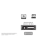
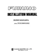
PI display side setting
1
Press MENU key to display “Menu”.
Select [NAV TOOL] => [PI] => [PI DISP SIDE] => select [HALF] or [FULL], and press ENT key.
Operation
(For MDC-5500 series)
1
Press VRM knob, and PI lines are displayed.
Bearing is displayed by figure on middle lower left of the display, and distance between PI lines is
displayed on middle lower right of the display during PI is displayed.
2
Turn the EBL knob to change the bearing.
3
Turn the VRM knob to change the interval between lines.
4
Press VRM knob, PI lines and values are not displayed.
HALF
PI T
134.2
゚
PI 1/4
0.500NM
FULL
PI T
134.2
゚
PI 1/4
0.500NM
Summary of Contents for MDC-5200 SERIES
Page 1: ......
Page 2: ......
Page 84: ... This page intentionally left blank ...
Page 118: ... This page intentionally left blank ...
Page 134: ... This page intentionally left blank ...
Page 146: ... This page intentionally left blank ...
Page 152: ... This page intentionally left blank ...
Page 160: ... This page intentionally left blank ...
Page 164: ...Chapter 10 Specifications MDC 5200 5500 Series 0093155002 00 10 4 RB806 RB807 Unit mm inch ...
Page 165: ...MDC 5200 5500 Series Chapter 10 Specifications 0093155002 00 10 5 RB808 RB809 Unit mm inch ...
Page 166: ... This page intentionally left blank ...
Page 178: ... This page intentionally left blank ...
Page 182: ......