background image

CVS-841/851 


Chapter 

Basic Operation


5.4.2.3 Horizontal split screen, Dual Frequency mode 


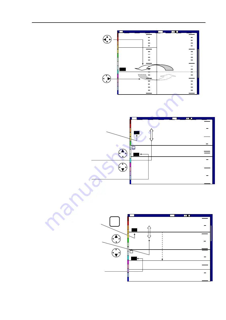
(1)  Press the VRM key. The last active   


VRM digital display will be highlighted. 

(2)  Press the UP or DOWN cursor key to   


move the VRM up or down. The VRM   


depth will be shown in the VRM digital   

 window. 

(3)  In case VRM stretches from one screen   


to the other, the VRM digit display indicates   


the depth of the new screen. 


5.4.2.4 Horizontal split screen, NORM/ZOOM image mode 

(1)  Press the VRM key. The last active   


VRM digital display will be highlighted. 

(2) 

(2) Press the UP or DOWN cursor 


key to move the VRM up or down.   


The VRM depth will be shown in the   

 VRM 

digital 

window. 

(3)  In case VRM goes beyond from one   


screen to the other, the VRM digit display   


indicates the depth of the new screen. 


1 3 0  

0  

1 0 0  

1 5 0  

2 0 0  

5 0  

4 3  

5 0  

7 5  

1 0 0  

1 2 5  

1 5 0  

2001/05/23(We

Image Speed 1/1

14:22:5

Shift 

High 

00

0

ZM 

(3) To change the VRM control 

from one to the other, use the 

following procedure: 

(4) To activate the left VRM, 


press the LEFT arrow key and 

  the RIGHT VRM, press the 


right arrow key. 

Figure 5.18 Operating the VRM in Vertical Split, NORM/ZOOM image mode (2) 

Figure 5.19 Operating the VRM in 

Figure 5.20 Operating the VRM in Horizontal Split, NORM/ZOOM mode 

Horizontal Split, Dual Frequency mode 

2 0 0  

0  

1 0 0  

1 0 0  

2 0 0  

0  

1 3 0  

2001/05/23 (Wed) 

Image Speed 1/1

14:22:56 

Shift 

Low 

00

0

High 

9 5  

7 5  

VRM 

Image Speed 1/1

1 3 0  

2001/05/23 (Wed)  14:22:56 

Shift 

Low 

00

0

9 5  

Moving VRM from upper 
screen to lower screen 

2 0 0  

0  


1 0 0  

1 2 5  

9 5  

7 5  

Hig

93132682-00 


5-15 

Summary of Contents for CVS-841

Page 1: ......

Page 2: ...cument number of the relevant sheet s and cover sheet are modified and the rest of the sheets are not changed The document number is shown in the footer area right or left bottom of each sheet 2003 2004 2005 2006 Koden Electronics Co Ltd All rights reserved No part of this publication may be reproduced transmitted translated in any form by any means without the written permission of Koden Electron...

Page 3: ...de after long periods of use Allergies can result from the inhalation of this dust therefore during inspection and cleaning it is advisable to use a mask z Static Electricity Static sensitive semiconductor devices are used in this unit Before changing the printed boards be careful not to damage any of these devices due to electrostatic build up from carpet clothes seats etc z Display Front Plate A...

Page 4: ...gnoring this sign may lead to injury to the human body or damage to the equipment Alarm Caution mark To handle the equipment ignoring this sign may lead to a malfunction of the equipment Caution Warning High Voltage mark To handle the equipment ignoring this sign may lead to electrical shock to the human body Prohibition mark This sign indicates that a specified action is prohibited The prohibited...

Page 5: ...requirement Chapter 1 General Information General features of the equipment Applicable standard Equipment configuration Software type name Chapter 2 Equipment Composition Standard equipment list Spare parts list Optional items list Available transducers list Chapter 3 Specifications Functional specifications Power supply requirements Environmental conditions External dimensions and weight Chapter ...

Page 6: ...IR function Operating the SHIFT key Using the Color Rejection function Setting the Alarm Function Operating the EVENT key Chapter 6 Using Menu The key switches used Operating procedure of the menu driven functions Confirming the factory initial settings Menu list Descriptions of the menu functions Display Automatic functions System Customize Initialize Simulator Chapter 7 Functional Registration D...

Page 7: ...nction Trouble shooting Setting the video threshold Chapter 9 Maintenance Periodical inspection and cleaning Chapter 10 Technical References Serial input data Details of input sentences Serial output data Data input output serial line Data input serial line Annex Sheets User setting list Factory default list ...

Page 8: ...of the screen This allows easy finding of a fish school near the sea bottom and observing the entire sounder image Bottom Zoom The generic term of zoomed sea bottom presentations that includes the Bottom Lock Bottom Discrimination and Bottom Zoom Color Alarm An audible alarm function that is triggered when the sounder detects a school of fish in a specific color The color can be specified by the o...

Page 9: ...ow frequency images are shown on the screen Echo Length Alarm An audible alarm function that is triggered when the sounder detects a school of fish of a certain length The length can be specified by the operator via the menu Fish Alarm An audible alarm function that is triggered when a school of fish which size and color are specified exists within a predetermined alarming depth range Fix Shift Us...

Page 10: ...r fishing and detection of weak schools of fish Log A gain control law in which receiver gain changes in a log law steep rise at first then gentle rise best suited for deep sea fishing Navigation Data B N Navigational data supplied from a navigator unit is shown such as ship s own position speed bearing waypoints etc Peak Hold A video processing method comparing two consecutive sonar video signal ...

Page 11: ...colors are shown in different colors from HIGH frequency transmission it indicates the fish school is sensitive to LOW frequency therefore a larger size of fish species Synchronization with External Sounder This function is used to reduce interference from other sounders operated on the same ship by synchronizing the transmission timing Through hull Installation A method of transducer installation...

Page 12: ... 841 851 Terminology Operation Manual 93132682 00 5 Zoom Range The name of a sub menu which allows selecting the zooming range of the following image modes Bottom Lock Bottom Discrimination and Bottom Zoom ...

Page 13: ...on Chapter 2 Equipment Composition Chapter 3 Specifications Chapter 4 Installation Chapter 5 Basic Operation Chapter 6 Using the Menu Chapter 7 Functional Registration Chapter 8 Trouble Shooting Chapter 9 Maintenance Chapter 10 Technical Reference Annex Sheets 93132682 00 Main Contents ...

Page 14: ...tion Manual General Information Chapter 1 General Information Contents Page No 1 1 General features of the equipment 1 1 1 2 Applicable standard 1 1 1 3 Equipment configuration 1 1 1 4 Software type name 1 2 93132682 00 Contents ...

Page 15: ...daytime and nighttime operations The screen size and its arrangement of the display unit vary according to the type TX RX module This module is composed of the transmitter and receiver sections contained in the display unit Changing the settings on the printed board of this module can change the transmitting power level and frequency The output power can be selected from 1 kW CVS 841C 851C or 3 KW...

Page 16: ... 38kHz or 40 kHz TD 504T 50kHz TD 504F 50kHz TD 754 75kHz CVS 841P CVS 851P 3kW TD 66 200kHz NOTE The output available from 200 KHz transducer type TD 66 used for CVS 841P 851P is 1 kW Dual Frequency TD Output Output Transducer TD 501C 50 200 kHz CVS 841C CVS 851C 1 kW TD 501T 3 50 200 kHz 1 4 Software type name CVS 841 Software type name Application KMC 82 System control CVS 851 Software type nam...

Page 17: ...52 5M 5m CW 328 5M 5m CW 60 10M 10m CW 60 10M 10m CW 154A 5M 5m TD Cable CW 836 3M J5 6 pin J2 6 pin J4 7 pin POWER J3 8 pin J6 5 pin Attached cable 10m GPS Sensor GPS 10A B Type KBG 1 2 B Type Navigator Unit Loran LR Junction Box JB 10 JB 12 AC DC Rectifier PS 006 10 8 31 2 VDC NOTE 2 Junction Box JB 32 Transducer Extension Cable VSV 2T11 3M Cable gland Speed Temperature sensor with cable and con...

Page 18: ...pter2 Equipment Composition Chapter 2 Equipment Composition Contents Page No 2 1 Standard equipment list 2 1 2 2 Spare parts list 2 1 2 3 Optional items list 2 1 2 4 Available transducers list 2 2 93132682 00 Contents ...

Page 19: ... hull Bronze with cable fitted 1 2Kg J7 101 Single frequency 1 6kg 2 TD Switch J8 201 Dual frequency 2 2kg 3 Inner hull kit MFB 04W Plastic applicable for 1KW only 1 5kg 4 Kingston kit MFB 05W Applicable for 1KW only 0 83kg 5 Junction Box for TD connections JB 32 For dual frequency 2 0kg JB 10 1 input 3 outputs 2 circuits 0 4kg 6 Junction Box for Navigator unit connection JB 12 1 input 3 outputs 3...

Page 20: ... hull dual frequency 1 5Kg CG 3 For wooden hull single frequency 2 5Kg CG 4 For wooden hull dual frequency 3 5Kg CG 16 For FRP hull single frequency 0 9Kg CG 18 For FRP hull dual frequency 1 8Kg 14 Cable gland CG 19 For wooden FRP hull single frequency 1 0Kg CVS 841 851 OM J Japanese 15 Operation manual CVS 841 851 OM E English CVS 841 851 SM J Japanese 16 Service manual CVS 841 851 SM E English 1...

Page 21: ... 3 Specifications Chapter 3 Specifications Contents Page No 3 1 Functional specifications 3 1 3 2 Power supply requirements 3 2 3 3 Environmental conditions 3 3 3 4 External dimensions and weight 3 3 93132682 00 Contents ...

Page 22: ...600 4000 200 step For 3 kW only 4000 7200 200 step 7200 8000 400 step Depth Unit meter hiro fathom Italian fathom One range selected 2 5 5 7 5 10 15 20 25 30 35 40 45 50 55 60 70 80 90 100 110 120 130 140 150 160 180 200 Zoom Bottom Range Depth Unit feet One range selected 10 15 20 30 40 50 60 80 100 120 140 160 180 200 220 240 260 280 320 360 400 450 500 550 600 650 Shift Automatic Manual Unit me...

Page 23: ...pth range shift Clock function Year Month Day Hour Minute Second NOTE CVS 841 has no Year Month Day a Day of the Week displays Depth unit 5 kinds m hiro fm I fm ft Bottom detection range 2 ways Within or outside the sonar display Depth sounding 3 ways Auto High frequency Low frequency Marker Variable range marker VRM Scale Guard zoom marker Division marker Time marker Color pattern Rotary controls...

Page 24: ...idity 93 3 40o C 2 Vibration The units are free from any functional deterioration or mechanical damage caused by the vibrating conditions stated below 2 5 Hz up to 13 2 Hz Amplitude 1mm 10 Maximum acceleration of 7 m s2 at 13 2 Hz 3 Water proof characteristic Display IPX5 Water jet proof 3 4 External dimensions and weight External dimensions Width x Hight x Depth CVS 841 320 12 5 8 x 340 13 3 8 x ...

Page 25: ...er 3 CVS 841 851 Specification 3 4 93132682 01 24 15 16 40 5 1 5 8 200 7 7 8 173 6 13 16 430 16 15 16 390 15 3 8 Unit in mm inch Weight 10 5 kg 23 0 lb Figure 3 2 External dimensions of CVS 851 Display Unit ...

Page 26: ...stallation 4 2 4 6 1 Table mounting 4 2 4 6 2 Flush mounting 4 4 4 7 Internal connections of the system 4 6 4 7 1 Preparation of DC Power cable 4 7 4 7 2 Preparation of TD cable 4 7 4 7 3 Connection of the transducers 4 8 4 7 3 1 About TD cable 4 8 4 7 3 2 Connecting the TD cable 4 8 4 8 Check up after installation 4 9 Appendix 1 Connector s pinouts 4 10 Appendix 2 Transducer installation 4 11 A1 ...

Page 27: ... for instance the LCD backlighting bulb is vulnerable against mechanical shock 4 4 Siting the units To achieve best operational performance the following factors must be considered 1 The display unit should be positioned in the location where the external situation can be viewed 2 Locate the display so that it provides easy viewing from all likely operator s positions 3 Select a position safe and ...

Page 28: ...led fixing knobs that fix the display unit to the mounting bracket 2 Remove the display unit from the bracket and place it on a flat and safe area 3 Place the mounting bracket to the place where the display unit is to be installed and fix the bracket with four 4 tapping screws 4 Reset the display unit on to the bracket and fix it using the two screws that were removed in step 1 Refer to the follow...

Page 29: ...ce space required for CVS 841 Unit in mm inch Fixing screws M5 screw 5 pcs Display Unit Mounting bracket Figure 4 3 Fitting detail of CVS 851 Washer Knurled fixing bolt Unit in mm inch 65 2 9 16 147 5 25 32 147 5 25 32 65 2 9 16 CVS 851 93132682 03 4 3 ...

Page 30: ...move four 4 plastic screw covers which are fitted on each corner of the display front face 4 Put the display on the opening and fix with four 4 tapping screws In case you use M4 screws to fix the display select an appropriate screw length that best suits fixing the unit to the panel thickness 5 Refit the coverings removed in step 3 Display Unit Screw covers 4 pcs Fixing screws M4 screws 4 pcs Figu...

Page 31: ...08 12 1 8 268 Fixing holes for M4 screw 4 pcs 16 5 8 16 5 8 300 11 13 16 16 5 8 16 5 8 Unit in mm i 306 12 1 16 nch Figure 4 7 Dimensions of opening and fixing holes for CVS 851 378 14 7 8 Fixing holes for M4 screw 4 pcs 360 14 3 16 418 16 7 16 410 16 1 8 9 3 8 9 3 8 9 3 8 9 3 8 392 15 7 16 Unit in mm inch 93132682 03 4 5 ...

Page 32: ... Input NMEA 0183 J6 External sounder DC Power Supply 10 8 31 2VDC TD Extension cable VSV 2T11 3M DC Power cable CW 253 2M AC DC Rectifier PS 006 AC Power Supply 100 110 115VAC 200 220 230VAC NOTE Dotted sections are optional items and wirings TD Transducer TD Junction Box JB 32 Cable gland Earthing lead OW7 1 6S 3M J7 TD cable CW 836 3M Figure 4 8 Inter connections of CVS 841 CVS 851 4 6 93132682 ...

Page 33: ...ion of TD cable 1 Cut off the cable sheath by 10 cm from end 2 Separate the braid from the strand and twist it to form a grounding lead 3 Strip each wire by 1 cm from end 4 Connect the TD cable CW 836 3M to the receptacle J7 at the display rear panel and press the rubber jacket onto the connector body to secure water tightness 10 cm Grounding lead Shield Red Green Black White High Frequency TD Shi...

Page 34: ...ith shielding copper braid The TD 2001D is PVC sheathed and has four core wires red white green black covered with shielding copper braid 4 7 3 2 Connecting the TD cable Single frequency TD except TD 2001D Connect the TD units to the Display unit as per the following diagram Solder the cables and apply winds of PVC tape to make sure of good isolation between the cables Single frequency TD TD 2001D...

Page 35: ...To J7 Display rear panel Red Green Shield White Black TD Low Freq 4 8 Check up after installation Before you turn the unit on check the following points to make sure the CVS 841 851 operates properly 1 Is the ship s supply voltage and current within the rated range 2 Is the transducer wiring normal No wrong connections no short circuits etc 4 Are the High and Low frequency transducers properly con...

Page 36: ...LSE 2 Speed B SPD VCC 3 Buzzer Output 0 BUZ0 4 Buzzer Output 1 BUZ1 5 NC 6 Water Temp B TEMP VCC 7 Water Temp Signal In TEMP SIG 8 Speed GND SPD GND 1 RS232C Data Input RXD 2 RS232C Data Output TXD 3 5V 5v 4 Ground GND 5 Not used NC 6 EVT EVT Not used 7 Ground GND 1 2 3 5 4 6 7 8 1 6 2 5 3 4 7 External Sounder Input J6 NMEA Nav Data Input J5 1 Ground GND 2 GPS Signal Out GPS OUT Not used 3 Ground ...

Page 37: ...eed are usually satisfactory Forward of the engine and in a flat area near the centerline of the boat are preferred Do not install the transducer behind water intakes other through hull fittings or irregularities in the hull NOTE High water line Water line when vessel pitches up most Low water line Water line when vessel pitches down most Keel Line Water Line length High water line Flat water line...

Page 38: ...rectifying tank to the ship s bottom before mounting the transducer to in the rectifying tank The more the tank protrudes the less the water turbulence The following drawing illustrates an example of the through hull installation Transducers Figure A 2 An example of the through hull transducer installation Cable gland Conduit pipe SGP 1 1 2 This pipe should b extended to the draft lin to the junct...

Page 39: ... 5 2 8 Changing the display position in the 3 division screen 5 9 5 3 Displaying the dual images 5 10 5 3 1 High Frequency and Low Frequency images 5 10 5 3 2 High Frequency NORM ZOOM images 5 10 5 3 3 Displaying Low Frequency NORM ZOOM image 5 11 5 3 4 Common key operations 5 11 5 3 5 Setting the partial zoom position in NORM ZOOM mode 5 12 5 4 Operating the VRM 5 12 5 4 1 Using the VRM in NORMAL...

Page 40: ...ction 5 16 Page No 5 7 Operating the SHIFT key 5 17 5 7 1 Setting Fix Shift mode 5 17 5 7 2 Setting the Auto Shift function 5 18 5 8 Using the Color Rejection function 5 18 5 9 Setting the Alarm Function 5 20 5 9 1 Depth Alarm 5 20 5 9 2 Fish Alarm 5 22 5 10 Operating the EVENT key 5 25 ...

Page 41: ...he degree of enhance effect for High Frequency image H FREQ GAIN control Varies the receiver gain of High Frequency image H FREQ STC DEPTH control Varies the effective range of High Frequency STC in depth H FREQ STC AMPD control Varies the intensity of High Frequency STC Turns on or off the unit and adjusts the brightness of the image EVENT key Registers or updates the event MENU key Turns on or o...

Page 42: ...ver gain of Low Frequency image RANGE switch Selects the depth range MODE switch Selects the image mode H FREQ STC DEPTH control Varies the effective range of High Frequency STC in depth H FREQ STC AMPTD control Varies the intensity of High Frequency STC H FREQ ENHANCE control Varies the degree of enhance effect for High Frequency image H FREQ GAIN control Varies the receiver gain of High Frequenc...

Page 43: ...ear month day a day of the week is not available in CVS 841 Figure 5 3 An example of image display shown on the screen 5 2 Getting started 5 2 1 Turning on 1 Turn the BRIGHTNESS control to the right until it clicks 2 Turn the control gradually to the right until the image brightness becomes an appropriate level 3 In a few seconds the following initial display appears showing the sounder type name ...

Page 44: ...depth range 1 Turn the RANGE switch to select the desired depth range which is shown on the screen for approximately 5 seconds NOTE Available depth range can be registered to each range number which is printed around the range scale selector switch To do so enter the menu in the following order For detail refer to Para 7 1 Depth Range registration MENU SYSTEM Depth Range Preset SW1 SW8 ENTER CVS 8...

Page 45: ...Frequency GAIN control High Frequency GAIN control CVS 851 High Frequency GAIN control Low Frequency GAIN control 200 Receiver gain is appropriate Receiver gain is short 140 43 130 0 50 100 150 2001 05 23 Wed Image Speed 1 1 The effect of GAIN control on the image High 0 0 0 0 Shift 14 22 56 Figure 5 7 Receiver gain controls and the images varied by the gain control 93132682 00 5 5 ...

Page 46: ... GAIN control on the control panel To vary the gain of H2 screen Press the UP or DOWN arrow key first A small pop up window will be displayed While the window is shown press the UP or DOWN key to decrease the gain UP for increasing the gain DOWN for decreasing the gain About 5 seconds after the key is pressed the window will disappear Press the Up or DOWN arrow key to change the setting Press Up o...

Page 47: ... species STC Amplitude Figure 5 8 Adjusting the STC depth STC Strength A C B Max Max Operational notes for STC amplitude adjustment 1 STC law A STC is not enough causing noise and unwanted residual weak echoes in shallow and mid depth zone to be shown 2 STC law B STC is appropriate causing unwanted echoes to be perfectly reduced while schools of fish are shown without degradation 3 STC law C STC i...

Page 48: ...esentation by narrowing the dynamic range of sonar video signals Rotating the ENHANCE control to the right causes the seabed and fish echoes to be displayed in dominant colors like red orange yellow etc for better recognition Rotating the control to the right causes the shades of colors to be widened for better definition of image colors NOTE Before using this function the MODE switch must be set ...

Page 49: ...y The Display sub menu will be shown 2 Select User 3 and press the Right arrow key to select the User 3 sub menu 3 Select a desired display mode among the following options a H 1 H 2 L b H 2 H 1 L c L H 1 H 2 d L H 2 H 1 e H 1 L H 2 f H 2 L H 1 The following is an example of the 3 division screen a H 1 H 2 L 4 Press the MENU key or press the Left arrow key three times to exit the menu 93132682 00 ...

Page 50: ...1 The available image has been set to NORM ZOOM mode Another form of a zoomed picture is available from Bottom Lock Bottom Discrimination Normal Zoom or Bottom Lock To change the setting refer to Para 7 2 2 Registering a ZOOM type 0 50 100 150 200 0 50 1 1 0 0 0 0 150 200 147 36 76 Low 2001 05 23 Wed Image Speed 1 1 14 22 56 Shift 0 0 0 0 High Figure 5 11 Dual Frequency images LOW Frequency image ...

Page 51: ...22 56 Shift 0 0 0 0 ZM Low Frequency Zoomed image Low Frequency Normal image Figure 5 13 Low Frequency NORM ZOOM image 150 5 3 4 Common key operations All menu driven functions can be operated using the MENU key and four way arrow keys Operating procedure are common to all functions which are as follows MENU 1 Press the MENU key to show the main menu list 2 Press the up or down arrow key to select...

Page 52: ...ted NOTE In case the digital display is shown in yellow press the VRM key to change the display green 5 Press either the up or down arrow key to set an upper limit depth Figure 5 14 Layout of NORM ZOOM mode display The picture on the right shows the display set up in this procedure Normal Low Frequency range on the right and Zoomed range on the left with zoom starting depth at 50 and zooming range...

Page 53: ...ital display is highlighted The highlighted digital display is also changed from one to the other Figure 5 15 Operating the VRM 200 43 130 0 50 100 150 High 2001 05 23 Wed Image Speed 1 1 1 4 2 2 5 6 Shift 0000 130 43 200 0 50 100 150 2001 05 23 Wed 1 4 2 2 5 6 Shift High 0 0 0 0 Image Speed 1 1 VRM VRM NOTE After 5 seconds if the VRM is not operated the VRM digital display returns to be non highl...

Page 54: ...split screen NORM ZOOM image mode VRM 1 Press the VRM key The last active VRM digital display will be highlighted 2 Press the UP or DOWN cursor key to move the VRM up or down The VRM depth will be shown in the VRM digital window VRM Figure 5 16 Operating the VRM in Ve Figure 5 17 Operating the VRM in Vertical Split NORM ZOOM image mode 1 rtical Split Dual Frequency mode VRM 0 50 100 150 200 43 130...

Page 55: ... 3 In case VRM goes beyond from one screen to the other the VRM digit display indicates the depth of the new screen 130 0 100 150 200 50 43 50 75 100 125 150 2001 05 23 We Image Speed 1 1 14 22 5 Shift High 0000 ZM 3 To change the VRM control from one to the other use the following procedure 4 To activate the left VRM press the LEFT arrow key and the RIGHT VRM press the right arrow key Figure 5 18...

Page 56: ...3 The pop up window will automatically disappear in 5 seconds after operation The pop up window shown Image speed digital display 0 50 100 150 200 Image Speed 1 1 Low 2001 05 23 Wed 14 22 56 Shift 0 0 0 0 1 1 Image Speed Figure 5 21 Image speed display 5 6 Activating the IR function When other sounders are operated on board the ship or on other ships nearby acoustic interference may be observed sh...

Page 57: ...om always appears within the screen whereby sounding range varies in order to keep the sounding image shown within the screen In practice when the sea bed becomes shallower reaching 40 of the depth range the image will be reset causing the sea bed depth displayed at approximately 60 of the entire range When the sea becomes deeper and the bottom falls to 90 of the depth scale the picture resets to ...

Page 58: ...han 40 or deeper than 90 of the full depth scale the entire image will be reset to 65 of the scale The words AUTO SHIFT appears here High 2001 05 23 Wed Image Speed 1 1 14 22 56 Auto Shift 90 40 150 100 50 20 Figure 5 25 The Auto Shift image 5 8 Using the Color Rejection function To reduce unwanted echoes like boat noise marine life those shown in weaker colors like pale blue pale green etc use th...

Page 59: ...t Resume 0 50 100 150 200 High 2001 05 23 Wed Image Speed 1 1 14 22 56 Shift 0 0 0 0 Color Color Figure 5 26 Color Rejection select display 1 Pressing the left arrow key rejects the specified color s and therefore is removed from the color bar shown on the left Pressing the right arrow key resumes the color s Color Rej Reject Resume 0 50 100 150 200 Image Speed 1 1 High 2001 05 23 Wed 14 22 56 Shi...

Page 60: ...e down arrow key to set the depth alarm ON Now you need to set upper and lower limit of the fish alarm Perform the following procedure in order Setting the Upper Alarm 1 Press the right arrow key to select Upper Alarm 2 Press further the right arrow key to show an alarm range window 3 Press the up or down arrow key to set the alarm depth 80 for example The upper end of the Depth Alarm bar will be ...

Page 61: ...0 Low Depth Alarm Set Upper Alarm range Select UPPER ALARM er Alarm 600 Press the up or down arrow key to set the depth Depth Alarm Upper Alarm Range 80 Lower Alarm 600 Upper Alarm 0 Figure 5 30 Selecting the Depth Alarm Setting the Lower Alarm 1 Press the ALARM key or Left arrow key to display the Depth Alarm window 2 Press the down arrow key to select LOWER ALARM 3 Press the right arrow key The ...

Page 62: ...larm bar white Alarmed object This fish school was inside of the alarm range and fulfilled the signal threshold Unalarmed object This fish school is within the alarm range but less than the specified length Figure 5 31 The Fish Alarm display Setting procedure Setting the Upper and Lower Fish Alarms 1 Press the MENU key to show the main menu 2 Press the up or down key to highlight FISH ALARM 3 Pres...

Page 63: ...row key to select the length To exit these menus from the bottom line press the left arrow key four times or press the MENU key twice Alarm Dept 報 h 警 Fish OFF Fish Alarm ON ON OFF Fish Alarm Selects the Lower Alarm menu Alarm Low 100 Fish Alarm Alarm Color Alarm Sig Length L Return to an upper menu Alarm Sig Length L Alarm Color Alarm Low 100 Alarm High 80 Fish Alarm Fish Alarm Alarm Sig Length L...

Page 64: ...larm Sig Length Long Lower Alarm 180 Upper Alarm 80 Fish Alarm Alarm Color Color Color Min Max For lower level color setting Alarm Color Max Color Color Min Color Color Min Max 魚警報色 色選択 色選択 下限 上限 Color Color Min Max Alarm Color Alarm Color Colors assigned by blue mark are assigned for alarming colors Figure 5 33 Setting the Fish Alarm Alarm signal color ALARM To exit from this menu press the ALARM...

Page 65: ...When the EVENT key is pressed a red line appears here to mark up the event High 2001 05 23 Wed Image Speed 1 1 1 4 2 2 5 6 Shift 0 0 0 0 0 50 100 150 200 Current nav information is shown here 35 36 115N 139 43 782E 25 2 o C 21 5Kt 315 0 35 36 115N 139 43 782E 0 0nm 0 0 00h00m 0 50 100 150 200 Image Speed 1 1 Shift High 1 4 2 2 5 6 2001 05 23 Wed 0 0 0 0 35 36 115N 139 43 782E 25 2 o C 21 5Kt 315 0...

Page 66: ... Rate 6 6 6 5 2 Image 6 7 6 5 2 1 Enhance 6 7 6 5 2 2 Color tone 6 7 6 5 2 3 Background color 6 7 6 5 2 4 White Line 6 7 6 5 2 5 Mix type 6 8 6 5 2 6 Flicker rejection 6 9 6 5 2 7 Past image 6 9 6 6 Display 6 9 6 6 1 A Scope 6 9 6 6 2 Information window 6 10 6 6 3 Zoom type 6 10 6 6 4 Zoom range 6 11 6 6 5 User settings USER 1 USER 2 6 11 6 6 6 User settings USER 3 6 11 6 6 7 Depth value 6 11 6 6 ...

Page 67: ...6 7 2 Auto shift 6 15 6 8 System 6 15 6 8 1 Time 6 15 6 8 2 Depth unit 6 15 6 8 3 Depth range preset 6 15 6 8 4 Draft setting 6 16 6 8 5 Bottom start 6 16 6 8 6 Bottom detection 6 16 6 8 7 Bottom detection adjust 6 16 6 8 8 Depth measurement 6 16 6 8 9 Sonic correction 6 17 6 8 10 Water Temp correction 6 17 6 8 11 Boat Speed correction 6 17 6 8 12 Speed data 6 17 6 8 13 Water Temp data 6 17 6 8 14...

Page 68: ...CVS 841 851 Chapter 6 Using menus 93132682 00 Contents 3 Page No 6 10 Initialize 6 19 6 10 1 User setting 6 19 6 10 2 Factory default 6 19 6 11 Simulator 6 20 ...

Page 69: ...switches 4 way arrow keys 1 Press the MENU key to show the Main Menu 2 Press the up or down arrow key to select a menu item and press the right arrow key to show its sub menu list 3 Press the up or down arrow key to select a sub menu or to select a numerical value 4 Press the MENU key or the left arrow key repeatedly until the normal screen display is shown The above procedures are illustrated as ...

Page 70: ...wn arrow key shifts the highlighted part up or down continuously Selecting a sub menu item Press the up or down arrow key to select an item Increasing or decreasing the value Selecting a sub menu item with value settings Figure 6 3 Common key switch operating order MENU Or Returning to a previous menu Press the MENU key or the left arrow key to return to a previous menu To return to the normal dis...

Page 71: ...to System Customize Initialize Simulator Initialize User Settings Factory Set To exit from the menu press the MENU key or the left arrow key 3 times MENU Press the MENU key and then press the up or down arrow key to select INITIALIZE Factory Set 1 2 3 4 The item highlighted is the factory initial setting For detail of the settings refer to Annex Sheets A2 Factory Initial setting list Figure 6 4 Se...

Page 72: ...Position Side Center Scale Value Large Small Time Mark OFF 10 sec 1 min Image Direction Image Partition Image Swap A B B A Color Bar Scale OFF ON Present Position OFF L L LOP Boat Speed OFF kt km h mph Bearing OFF ON Water Temp OFF o C o F Water Temp Graph OFF ON Event Position OFF ON Event Distance OFF ON Event Direction OFF ON Display Note1 The Information Window feature is not available in CVS ...

Page 73: ...F ON IMAGE SPEED Key OFF ON IR Key OFF ON SHIFT Key OFF ON COLOR REJ Key OFF ON ALARM Key OFF ON EVENT Key OFF ON Customize Panel Brightness 1 5 5 5 User Setting 1 4 Initialize Factory Default 1 4 Simulator OFF ON 6 5 Descriptions of the menu functions 6 5 1 Transmission 6 5 1 1 Pulse Width H L Definition and detectable depth of a sounder varies depending on the pulse width The CVS 841 851 series ...

Page 74: ...chool of fish The echo signal is weakened due to power reduction Normal Low Figure 6 5 Reduction of output power 6 5 1 3 PRR Pulse Repetition Rate This function changes the rate of transmission per minute Using this function you can eliminate the false echo caused by other sounder s transmission working on nearly the same transmission rate Selections 1 Fastest 10 Slowest Initial setting 1 2 10 Rea...

Page 75: ...uency or Low Frequency on the operation panel to a desired level 6 5 2 2 Color tone Varies the sonar color tone in 3 ways as follows Selections 1 2 3 steps 1 16 colors KODEN standard color 2 16 colors White not inclusive 3 8 colors KODEN standard color Initial setting 1 6 5 2 3 Background color The background color of the screen can be changed in 9 ways Selections 1 9 1 Pale Blue 2 Marine Blue 3 B...

Page 76: ... Mixed image A COMPARISON mode This mode displays the result of the comparison between HIGH and LOW frequency echoes If those echoes are overlapped at the same depth the resultant colors are displayed in mixed colors However if the HIGH frequency echo is painted in red strongest color the mixed color will also be red to show the echoes are from small fish If the mixed fish school is partly display...

Page 77: ...jection Rejects flicker on the screen while the screen is moving Selections OFF and ON Initial setting ON 6 5 2 7 Past image Enables gain control over past images shown on the screen This feature allows the user to go back and analyze ground that has already been covered in greater detail including density of fish school activity and even type of fish Selection OFF and ON Initial setting ON 6 6 Di...

Page 78: ...ature and own ship s speed indications 6 6 3 Zoom type BTM Bottom The bottom image is always fixed in the lower part of the screen even though the depth changes BD Bottom Discrimination Even though the sea bottom depth changes the top surface of the sea bottom is displayed as a flat surface in order to serve as a reference A range of measurement is also taken underneath the reference This results ...

Page 79: ...0 320 360 400 450 500 550 600 650 Initial setting 5 6 6 5 User settings USER 1 User 2 User specific settings can be allocated to USER 1 and USER 2 functions The following image mode can be allocated to these functions Selections H MIX L MIX H L MIX H EN L EN H BTM L BTM H B D L B D H ZOOM L ZOOM H B Z L B Z Initial setting USER 1 H BTM L BTM USER 2 H B D L B D 6 6 6 User settings USER 3 The 3 Divi...

Page 80: ...he size of the depth scale value Selection Large Small Initial setting Small 6 6 12 Time Mark Selects the time marker on or off or time unit every 10 seconds 1 minute Selections OFF 10 sec 1 min Initial setting 10 sec 6 6 13 Image direction Selects the direction of image movement Selections Initial setting 6 6 14 Image partition Selects the image split way either in a vertical split or a horizonta...

Page 81: ...s OFF kt kmh mph Initial setting OFF 6 6 19 Bearing Turns on or off the bearing of your boat Selections OFF ON Initial setting OFF 6 6 20 Water Temp Turns on or off water temperature and selects its unit Selections OFF o C o F Initial setting OFF 6 6 21 Water Temp graph Turns on or off the water temperature graph To use this function an appropriate water temperature sensor must be connected to the...

Page 82: ... Selections OFF ON Initial setting OFF 6 6 24 Event direction Turns on or off the direction of Event to own ship Selections OFF ON Initial setting OFF 6 6 25 Event elapsed time Turns on or off the time elapsed from Event position Selections OFF ON Initial setting OFF 6 7 Automatic functions There are two auto functions available for range selection or depth shift control Selections Auto Range Auto...

Page 83: ...d of settings Setting items Year Month Day Hour Min and Sec Initial setting 2001 01 01 00 00 00 6 8 2 Depth unit Selects the depth unit of measure from the following options Selections m fm J fm l fm ft Initial setting m 6 8 3 Depth range preset The following depth range values are registered depending on the depth unit 1 For meter hiro fathom Italian fathom Applicable to all models 2 5 5 7 5 10 1...

Page 84: ...as the depth from the sea surface Water surface Transducer Figure 6 17 Draft Line Selections 0 0 to 25 5 applicable to all depth units Initial setting 0 0 Draft 6 8 5 Bottom start Sets up the starting depth of the seabed detection Once set the fish echo or the seabed shallower than the set up depth will not be detected Selections 0 20 0 Applicable to all depth units Initial setting 5 0 6 8 6 Botto...

Page 85: ...ed sensor or from a navigation receiver via the connector described below INT This connector is used when the speed data is taken from a dedicated speed sensor ST 80 1 90 1 100 1 When no data is supplied 0 0 will be shown in the speed data window EXT This connector is used when the speed data is supplied from an external sensor or navigation receiver in NMEA format When no data is supplied xxx x w...

Page 86: ...cteristic according to your fishing type type of fish etc Available characteristics are Linear type and 8800 type Logarithmic law Linear type The receiver gain varies in a linear law in proportion to the Gain control best suited to shallow water fishing or detecting weak echoing school of fish 8800 type The receiver gain varies in a logarithmic law rapid in change at the beginning and slow afterwa...

Page 87: ...itialize 6 10 1 User setting This sub menu is used to register the menu driven functions specified by the user to internal registers named User 1 through to User 4 To register 1 Press the up or down arrow key to select User Setting and then select User Setting 1 for example 2 Press the right arrow key to select Registration Execute and then press the right arrow key The menu display disappears and...

Page 88: ...nu display disappears and the system is now set to the selected Factory Default 4 To change the setting repeat the above procedures from step 1 6 11 Simulator Displays simulated sonar echoes for training and exhibition purposes of CVS 841 851 series sounder To display the simulated echoes select ON and exit the menu To turn off the Simulator select OFF and exit the menu Selections OFF ON Initial s...

Page 89: ...tration 7 4 7 2 1 Registering functions to USER 1 and 2 7 4 7 2 2 Registering functions to USER 3 7 6 7 2 3 Registering a ZOOM type 7 7 7 2 3 1 BTM NORM display 7 9 7 2 3 2 BD NORM display 7 9 7 2 3 3 ZOOM NORM image 7 9 7 2 3 4 B Z image 7 10 7 3 Setting the Enhance effect 7 10 7 4 Setting the 3 Division Screen H L and gain 7 12 93132682 00 Contents ...

Page 90: ... down arrow key to highlight SYSTEM and press the right key to show the SYSTEM sub menu and press the right key to show the SYSTEM sub menu 3 Press the up or down key to highlight DEPTH RANGE PRESET and press the right arrow key to show the range registration list 3 Press the up or down key to highlight DEPTH RANGE PRESET and press the right arrow key to show the range registration list 4 Press th...

Page 91: ...0 280 290 300 310 320 330 340 350 360 370 380 390 400 450 500 550 600 650 700 750 800 850 900 950 1000 1100 1200 Additional ranges for 3kW models 1300 1400 1500 1600 1700 1800 1900 2000 2100 2200 2300 2400 2500 2600 2700 2800 2900 3000 2 For feet Applicable to all models 20 40 60 80 100 120 140 160 180 200 220 240 260 280 300 320 340 360 380 400 440 480 520 560 600 640 680 720 760 800 840 880 920 ...

Page 92: ...epth Unit M Depth Range Preset Draft Setting 0 Bottom Start 0 Bottom Detection Adjust Bottom Detection Inside Depth Measurement Auto Sonic Correction 0 Boat Speed Correction 0 Water Temp Correction 0 Menu Transmission Image Display Auto System Customize Initialize Simulator First page sub menu System Time Depth Unit m Depth Range Preset Draft Setting 0 0 Bottom Start 0 0 Bottom Detection Adjust Bo...

Page 93: ...e ct the item H EN Enhance for example Menu Display User 1 User 2 H EN Menu Display User 1 User 2 H EN CVS 841 CVS 841 CVS 851 CVS 851 User 1 L MIX H MIX H L MIX H EN L EN H BTM L BTM H B D L B D H ZOOM L ZOOM H B Z L B Z Menu Transmit Image Display Auto System Customize Initialize Simulator Display A Scope OFF InformationWindow OFF ZoomType ZOOM Zoom Range 2 5 User 1 H EN User 2 B D User 3 H 1 H ...

Page 94: ...1 L H MIX MIX NORM Enhance NORM L NORM H LK H NORM H LK L BZ L Scale Position L MIX H MIX H L MIX H EN L EN H BTM L BTM H B D L B D H ZOOML ZOOM H B X L B Z Acronym NORM Normal Display BZ Bottom Zoom Display LK Bottom Lock Display MIX Video Mixed Display Figure 7 6 Available image modes in the USER 1 menu Figure 7 7 Fixing the entry to the USER 1 menu MENU Or Display A Scope OFF InformationWindow ...

Page 95: ...1 CVS 851 4 This completes the image mode settings User3 H 1 H 2 L H 2 H 1 L L H 1 H 2 L H 1 H 2 H 1 L H 2 H 1 L H 2 Display A Scope OFF InformationWindow OFF ZoomType ZOOM Zoom Range 2 5 User 1 H EN User 2 B D User 3 H 1 H 2 L Depth Value Large Depth Value Position Bottom Scale Single Scale Position Side Menu Transmit Image Display Auto System Customize Initialize Simulator Display A Scope OFF Zo...

Page 96: ... 841 CVS 851 The screen layout of available zoom mode displays are as follows B Z Zoom Type BTM BD ZOOM Menu Transmit Image Display Auto System Customize Initialize Simulator B Z Zoom Type BTM BD ZOOM Figure 7 8 Registering a ZOOM type Display cope OFF mationWindow OFF A S Infor ZoomType Bottom Zoom Us Us Us D D Sc Scal Range 5 0 er 1 H FREQ MIX er 2 B D er 3 H 1 H 2 L epth Value Large epth Value ...

Page 97: ...S 851 For Low Frequency settings CVS 841 CVS 851 Figure 7 9 Available ZOOM mode screen layout Mode switch setting NORM H BTM H NORM H BD H NORM H ZOOM H B Z H Available Image Layout Mode switch setting Available Image Layout NORM L BTM L NORM L BD L NORM L ZOOM L B Z L 7 8 93132682 00 ...

Page 98: ... image is shown flat with its upper and lower parts shown at a specified depth The fish echoes are shown within the range set up by the user 1 4 2 2 5 6 Zoom range bar Orange 2002 09 04 Wed 0 0 0 0 Shift Image Speed 1 1 ZM 5 0 1 0 0 1 5 0 2 0 0 150 Nor 5 0 0 5 0 1 0 0 1 1 0 0 0 0 0 Seabed Zoomed range BD image Normal image Figure 7 11 BD NORM image 7 2 3 3 ZOOM NORM image This mode of image is a c...

Page 99: ...ou wish to change the setting press the right arrow key and then press the up arrow key You can choose 35 45 55 and 65 dB each time you press the key 6 Press the MENU key or the left arrow key three times to fix the setting and exit the menu 1 4 2 2 5 6 2002 05 04 Wed 0 0 0 0 Shift Image Speed 1 1 High 5 0 1 0 0 1 5 0 2 0 0 150 Zoomed depth range 1 4 2 2 5 6 2002 09 04 Wed 0 0 0 0 Shift Image Spee...

Page 100: ...e Line OFF Menu Transmission Image Display Automatic System Customize Initialize Simulator Menu Image Enhance 25 db Color Tone 1 Background Color 1 Mix Type A Flicker Rejection OFF White Line OFF Transmission Image Display Automatic System Customize Initialize Simulator Past Image OFF Figure 7 15 Setting the Enhancement effect 93132682 00 7 11 ...

Page 101: ... up or low arrow key to display the gain control window 6 While this window is displayed the gain control is effective To increase the gain press the up arrow key To decrease the gain press the down arrow key The window will disappear 5 seconds after the last key operation has been done NOTE In the Shift mode the up and down arrow keys are solely used for the image shift operation To attempt adjus...

Page 102: ...to the down arrow key for decreasing the gain The gain index number varies from 0 0 to 10 0 with 0 1 increment The High Frequency 2 gain control can be made with up and down keys 1 1 5 5 2 2 H 1 IMAGE SPEED 1 1 1 4 2 2 5 6 SHIFT 0000 H 2 L 1 1 0 0 0 0 5 5 1 1 5 5 2 2 0 0 H 2 GAIN 2 6 Up arrow key The current setting is being set to Shift mode Press the SHIFT key to turn this mode off Down arrow ke...

Page 103: ...pter 8 Trouble Shooting Chapter 8 Trouble Shooting Contents Page No 8 1 Information required for service 8 1 8 2 Self check function 8 1 8 3 Trouble shooting 8 1 8 4 Setting the video threshold 8 3 93132682 00 Content ...

Page 104: ...failure Call for service 8 3 Trouble shooting The following table provides information about first line check schedules to locate a faulty area and gives remedial measure s where applicable Table 7 1 Fault finding chart for CVS 841 851 Faults detected Possible cause of the failure Remedial action against negative result Equipment does not turn on 1 Is the fuse blown 2 Does the power supply voltage...

Page 105: ...Select the suitable setting No present position is shown 1 Is the L L or LOP coordinate selected in the Display Present Position menu 2 Is the necessary NMEA 0183 Nav data GGA GLL GTD RMC supplied via the receptacle J5 SER DATA at the rear panel 1 Select the suited coordinate 2 Connect a Navigator unit that supplies NMEA 0183 format with suitable sentence GGA GLL GTD RMC No ship s speed data shown...

Page 106: ...cope in which a threshold graph is shown The threshold level is being preset to 40 for both HIGH and LOW frequencies Adjustable range is from 80 to 40 b Use the up and down key to allow the graph to touch the right end of the green bottom video Read the threshold value at this time c Again press the down arrow key to reduce the value by 6 This setting is considered to be an optimum level that cove...

Page 107: ...om detection threshold window High Freq 3 Bottom detection threshold is appropriately set 1 Setting too low Approx 80 A school of fish is mistakenly detected as a bottom 2 Setting too high Approx 40 A bottom is not detected 4 Set the threshold curve to be tangential with the bottom echo The threshold curve obtained by reducing the threshold level by 6 Figure 8 1 Setting the bottom detection thresh...

Page 108: ...CVS 841 851 Chapter 9 Maintenance Chapter 9 Maintenance Contents Page No 9 1 Periodic inspection and cleaning 9 1 9 1 1 Monthly check 9 1 9 1 2 Yearly check 9 1 93132682 00 Contents ...

Page 109: ...the display screen is dirty clean the screen with a soft cloth damped with anti static agent or pure water Do not use a dry cloth as it causes static build up which accumulates dust 9 1 2 Yearly check Inspect the surface of the transducer for any marine growth If so remove the growth using an appropriate tool taking care not to scratch the surface Harsh scratching of the transducer surface may cau...

Page 110: ...age No 10 1 Serial input data 10 1 10 2 Details of input sentences 10 1 10 3 Serial output data 10 3 10 3 1 Details of output data sentences 10 3 10 3 2 Output signal specification 10 3 10 4 Data input output serial line 10 5 10 5 Data input serial line 10 5 93132682 01 Contents ...

Page 111: ...alker devic code 0 Positioning unable 1 GPS positioning Start of sentence 2 DGPS positioning 3 8 Not acceptable GLL Geographic position Ver 1 5 2 0 GLL xxxx xxx a xxxxx xxx a A a hh CR LF Sentence Latitude Longitude Checksum name N North E East This field is not used S South W West Mode identifier A Valid Talker devic code This field is not used Start of sentence GTD Geographical position Loran C ...

Page 112: ... xxxx xxx E W xxx x xxx x xxxxxx hh CR LF VTG Course and water speed Ver 1 5 VTG xxx x T xx x N a hh CR LF Sentence Ship s bearing Ground speed Checksum Name True KNT Mode identifier These fields are not used Talker device code Start of sentence UTC of position fix hr min sec A Data valid V Data invalid Latitude N North S South Longitude E East W West Speed over ground knots Course over ground deg...

Page 113: ... Output current 5 mA Maximum Data refreshing rate 1 second Name Version Sentence name DBS Depth data From the sea surface to the seabed Ver 1 5 SD DBS xxxx x f xxxx x M xxx x F hh CR LF Sentence Depth meters Checksum name Depth feet Depth fathom Talker device code Start of sentence D0 D1 D2 D3 D4 D5 D6 D7 Logic 0 4V Logic 1 0 5V Data Bit ASCII Code Start Bit Stop Bit NOTE Checksum is a total sum o...

Page 114: ...e Depth m Draft level m Talker device code Start of sentence MTW Water temperature Ver 1 5 SD MTW xx x C hh CR LF Sentence Checksum name Temperature o C Talker device code Start of sentence TLL Target latitude and longitude Ver 2 0 SD TLL xx xxxx xxx a xxxxx xxx a hhmmss ss a a hh CR LF Sentence Latitude Longitude UTC data Checksum name N North E East Reference target fixed to T S South W West Tar...

Page 115: ...61162 1 standard signal can be transmitted Device RS232C Driver IC Type 2SA1162 10 5 Data input serial line Port name J5 The connector used Type LTWD 06BFFA L180 Serial Data input listener side The IEC 61162 1 standard signal can be received Input load 470 ohms Device Opto coupler type TLP181 G8 Toshiba RXD RTN 470 A Data Input B Data Input Vcc Serial data input circuit TLP181 G8 TXD RXD RTN 470 A...

Page 116: ...nnex Sheets Annex Sheets Contents Page No A1 User setting list A 1 A2 Factory default list A 3 A2 1 Dedicated key functions A 3 A2 2 Menu functions A 3 A2 3 Depth range preset default values A 5 93132682 05 Contents ...

Page 117: ... Scale Scale Position Scale Value Time Mark Image Direction Image Partition Image Swap Color Bar Scale Present Position Boat Speed Bearing Water Temp Water Temp Graph Event Position Event Distance Event Direction Display Note1 The Information window feature is not available in CVS 841 Event Elapsed Time Auto Range Automatic Auto Shift Time Note2 Depth Unit Depth Range Preset Draft Setting Bottom S...

Page 118: ...ette Color Red Green Blue Panel Lock H FREQ GAIN control H FREQ ENHANCE Control H FREQ STC DEPTH Control H FREQ STC AMPTD Control L FREQ GAIN Control L FREQ ENHANCE Control L FREQ DEPTH Control L FREQ STC AMPTD Control RANGE switch MODE switch VRM key IMAGE SPEED key IR key SHIFT key COLOR REJECT key ALARM key Customize Event KEY Note In case the palette number palette color column is not sufficie...

Page 119: ...rmal PRR 1 1 1 1 Image Enhance 25 25 25 25 Color Tone 1 1 1 1 Background Color 1 1 1 1 White line OFF OFF OFF OFF Mix Type C C C C Flicker Rejection ON ON ON ON Past Image ON ON ON ON A Scope OFF OFF ON ON Information Window Note1 OFF OFF OFF OFF Zoom Type BTM BTM BTM BTM Zoom Range 5 5 5 50 User 1 BTM BTM BTM BTM User 2 D B D B D B D B User 3 H 1 H 2 L H 1 H 2 L H 1 H 2 L H 1 H 2 L Depth Value La...

Page 120: ...r to A2 2 3 Depth Range Preset default values for default values Draft Setting 0 0 0 0 0 0 0 0 Bottom Start 5 0 3 0 5 0 17 0 Bottom Detection Inside Range Inside Range Inside Range Inside Range Depth Detection Adjust H 40 L 40 H 40 L 40 H 40 L 40 H 40 L 40 Depth Measurement Auto Auto Auto Auto Sonic Correction 0 0 0 0 Water Temp Correction 0 0 0 0 0 0 0 0 System Note2 CVS 841 has no Year Month Day...

Page 121: ... fm Factory Default 3 m Factory Default 4 ft 1 20 10 20 60 2 50 30 50 160 3 80 50 80 260 4 100 65 100 320 5 200 130 200 640 6 500 330 500 1600 7 1000 650 1000 3200 1kW 8 1200 1000 1200 4000 1 20 10 20 60 2 50 30 50 160 3 80 50 80 260 4 100 65 100 320 5 200 130 200 640 6 500 330 500 1600 7 1000 650 1000 3200 3kW 5kW 8 1500 1000 1500 5000 ...

Page 122: ......

Reviews: