Operating manual PxtFX active energy management device
V1.1DE/EN
22
5 Commissioning
En
glish
5.2.3
Connecting the I/O communication interface (X3)
Basic information
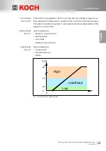
• The active levels of all inputs and outputs are configured to "high active" by default
(customer-specific settings may differ).
• Through the digital inputs and outputs, it is possible to switch certain functions of
the PxtFX devices on or off and to evaluate status messages.
• The GND supply voltage and GNC digital signals must be directly connected.
Connectable
conductors
• Conductor cross-section, single-core, according to AWG: 24…16.
• Conductor cross-section, single-core: 0.205 mm²…1.31 mm².
• Conductor cross-section, fine-core, according to AWG: 24…16.
• Conductor cross-section, fine-core: 0.205 mm²…1.31 mm².
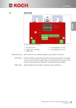
Fig. 13: Connector X3
Pin Signal
Configuration of standard device/Comment
24 V External In
±15 % Tolerance
min. 8 V (if only parameterization is to be
performed)
2
GND External
3
Digital Out 1 (max. 50 mA)
24 V External Out
4
Digital Out 2 (max. 50 mA)
Ready
5
Digital Out 3 (max. 50 mA)
Error status (low in case of error)
6
Digital In 1
Parameter switchover
7
Digital In 2
Charge inhibit (low for inhibit)
8
Digital In 3
Enable (high for enable)

