


Operating manual PxtFX active energy management device
V1.1DE/EN
18
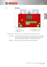
5 Commissioning
En
glish
• As long as the external storage is charged with energy, it may fundamentally not
be connected to the PxtFX active energy management device.
• It is possible to supply the device via an external 24 V power supply unit.
Cable
• The connecting cables (cross-section to comply with your national standards)
between the PxtFX active energy management device and the DC link of the
application must be shorter than 2.0 m, must be laid as a twisted pair and must be
secured against short circuits.
• Power cables and signal cables must be laid in separate cable ducts.
• Securing/Useable cross-sections:
If possible, the cross-sections for connecting the PxtFX should be selected to
match the connecting cable of the frequency inverter.
If this is not possible, there are two options:
1.) Select a short-circuit-proof cable with reinforced insulation.
2.) Install an additional fuse in the supply line.
It should be noted that the energy storage solution is internally fused with 20 A.
An additional fuse must therefore be >20 A.
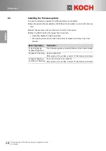
5.2.1
Connecting the DC circuit (DC link) and brake chopper (X1)
Connectable
conductors
• The cable length must be shorter than 2 m.
• Clamping range: 0.25 mm²…6 mm².
• Conductor cross-section according to AWG: 24…8.
• Conductor cross-section, single-core: 0.5 mm²…6 mm².
• Conductor cross-section, fine-core: 0.5 mm²…6 mm².
• Conductor cross-section with wire end ferrule and collar according to
DIN 46228/4: 0.25 mm²…6 mm².
• Conductor cross-section with twin wire end ferrule according to
DIN 46228/1: 0.25 mm²…6 mm².


