Operating manual PxtFX active energy management device
V1.1DE/EN
20
5 Commissioning
En
glish
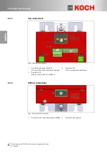
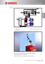
Make sure there is no voltage between terminal "Drive +" (X1, pin 2) and terminal
"Drive -" (X1, pin 3).
Connect the negative pole at the DC circuit (DC link) output of the application in
loop through the ferrite sleeve
to "Drive -" (X1, pin 3) on the active energy
management device.
Connect the brake chopper output of the application in loop through the ferrite
sleeve
to "Drive BRC" (X1, pin 1) on the active energy management device.
Brake chopper output has switched negative potential of the DC circuit
(DC link).
Please note:
This step is not required for a "fixed setting of operating voltage" on the DC
circuit (DC link).
Connect the positive pole at the DC circuit (DC link) output of the application in
loop through the ferrite sleeve
to "Drive+" (X1, pin 2) on the active energy
management device.
Supply the DC circuit (DC link) with voltage.
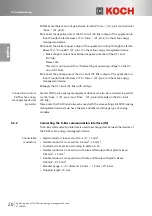
Connect two or more
PxtFX active energy
management devices
in parallel.
Several PxtFX active energy management devices can also be connected in parallel
via the "Drive +" (X1, pin 2) and "Drive -" (X1, pin 3) terminals on the DC circuit
(DC link).
Please note that PxtFX must always be used with the same settings. All PxtFX energy
management devices must have the same number and storage type of energy
modules.
5.2.2
Connecting the K-Bus communication interface (X2)
The K-Bus communication interface is used to exchange data between the devices of
the PxtFX active energy management device.
Connectable
conductors:
• Rigid conductor cross-section: 0.2 mm²…1.5 mm².
• Flexible conductor cross-section: 0.2 mm²…1.5 mm².
• Conductor cross-section according to AWG: 24…16.
• Flexible conductor cross-section with wire end ferrule without plastic sleeve:
0.25 mm²…1.5 mm².
• Flexible conductor cross-section with wire end ferrule with plastic sleeve:
0.25 mm²…0.75 mm².
• Mandrel gauge a × b / diameter: 2.4 mm × 1.5 mm / Ø 1.6 mm.
• Stripping length: 10 mm.


