background image

3.4  FUNCTION BUTTON

The  Function  Button  activates 

IC-IP-S.1.0

´s  special  function.  Factory  Reset  can  be  activated.  Device 

settings of 

IC-IP-S.1.0

 can be reset to manufacturer default values with the Factory Reset function. During 

the firmware update procedure the Function Button has to be pressed for Boot Mode activation.

3.4.1  FACTORY RESET

A long press (≈ 15 sec) of the Function Button soon followed by a short press (≈ 3 sec) executes the Factory 
Reset.  A er  the  first  press,  the  LED  display  lights  like  described  in  Table 

1

.  A er  the  second  press,  all 

parameters  will  be  set  to  factory  default  (incl.  Individual  Address).  Subsequently,  LEDs  indicate  normal 
operation again.

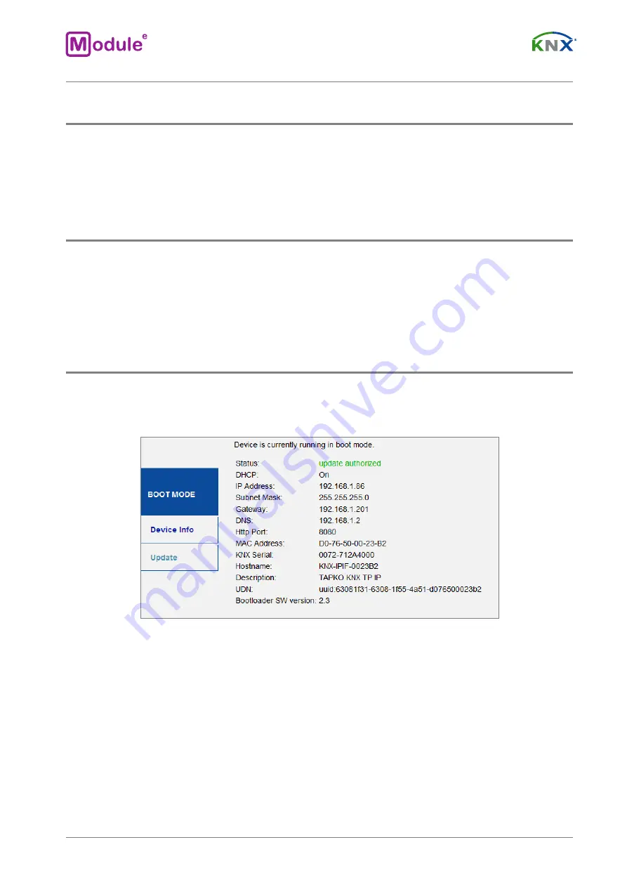
3.4.2  BOOT MODE ACTIVATION

For  Boot  Mode  activation  the  firmware  update  process  must  be  executed.  During  the  process,  the 
Function Button must be pressed to enter Boot Mode (see chapter 5.4).

Figure 2.

 Boot Mode is active

page 10

module-electronic.ru

Summary of Contents for Module IC-IP-S.1.0

Page 1: ...module electronic ru KNX IP INTERFACE IC IP S 1 0 Application Program ver 1 0 User Manual ver 1 0 User Manual...

Page 2: ...assignment 9 3 4 Function button 10 3 4 1 Factory reset 10 3 4 2 Boot mode activation 10 3 4 3 LED status display 11 4 ETS database parameters 12 4 1 General 12 4 2 IP con guration 12 5 Web front end...

Page 3: ...nd manage devices on the KNX network Protocol KNXnet IP Up to 4 connections simultaneously Ethernet 10 100 BaseT IP LED status indication Long telegrams with up to 240 bytes APDU length are supported...

Page 4: ...cable TP1 0 8 Supported protocols KNXnet IP ARP ICMP IGMP HTTP UPnP discovery UDP IP TCP IP DHCP AutoIP KNX physical address by default 15 15 0 Power supply via KNX bus 21 30 DC Consumption on the KNX...

Page 5: ...K OFF No IP connection 2 Bus state KNX TP Green KNX TP line OK OFF KNX TP line not connection 3 Telegram tra ic IP Green blinking Telegram tra ic Red blinking Transmission error OFF No telegram tra ic...

Page 6: ...g the device Even when the device is turned o the output terminals can be live Do not connect to the outputs a load that exceeds the recommended values The design of the device meets the requirements...

Page 7: ...o ers the possibility for point to point connections for the ETS KNXnet IP Tunneling and or between supervisory system and KNX installation The KNXnet IP device management enables KNXnet IP device con...

Page 8: ...sses always have to be assigned in the range of subline addresses For more information about additional Individual Addresses for tunneling please refer to IP Tunneling Address Assignment To program de...

Page 9: ...ot Mode is active successive pressing the Programming Button will turn on and o Programming Mode and Programming LED To con gure the device an interface connection IP USB to the KNX bus system is requ...

Page 10: ...s 15 sec of the Function Button soon followed by a short press 3 sec executes the Factory Reset A er the rst press the LED display lights like described in Table 1 A er the second press all parameters...

Page 11: ...NX TP orange Table 1 LED status display for factory reset a er rst button press Number LED Colour Comment 1 State IP green 2 Bus state KNX TP blinking green 3 Telegram tra ic IP blinking green no the...

Page 12: ...ETS Parameter Setting Factory Default Comment Host name 30 characters allowed KNX IP Interface Field to enter the device name providing an easy search of the devices by ETS by Windows Network and by K...

Page 13: ...on guration tab parameters DHCP o ETS Parameter Setting Factory Default Comment IP address 0 255 0 255 0 255 0 255 0 0 0 0 IP byte 1 to 4 manual input Subnet mask 0 255 0 255 0 255 0 255 255 255 255 0...

Page 14: ...abort or wait for the 10 min timeout 5 1 ACCESSING THE IC IP S 1 0 WEB FRONT END There are three ways to access the IC IP S 1 0 It can be accessed like a Microso Windows UPnP network device Windows7...

Page 15: ...d IC IP S 1 0 appears in the Windows Network A click on the IC IP S 1 0 network device opens the web front end with the standard web browser If IC IP S 1 0 is not visible as an UPnP network device a m...

Page 16: ...respectively in the URL bar has to be entered without brackets http IP address HTTP port Example1 DHCP is not used With the latest ETS download the IP address was set to 192 168 1 32 and HTTP port wa...

Page 17: ...m of AA BB CC XX YY ZZ and the pre set HTTP port to be entered in the browser s URL bar as described here without brackets http knx ipif XXYYZZ HTTP port Example1 On the housing side UIMip is labelled...

Page 18: ...b it is easy to distinguish the regarded device with a certain IP address or MAC address or serial number from other similar devices in the same IP network Four tunneling addresses can be set ETS sets...

Page 19: ...update Boot Mode is still active a er device reset and a er factory reset To exit Boot Mode it is necessary to enter the Update tab of the web front end Then either the rmware update has to be complet...

Page 20: ...3 Request update Step 4 When the request update button appears it has to be pressed to select the update le and enter Boot Mode Figure 12 Update authorized Step 5 The update le can be selected and upl...

Page 21: ...g to the host s Individual Address assignment the rst tunneling address additional Individual Address of the IC IP S 1 0 can only be set by ETS Please make sure The additional Individual Addresses for...

Page 22: ...t the remaining three tunneling addresses basing on the rst tunneling address as follows 6 STATE OF DELIVERY 6 1 DEFAULT FACTORY SETTING General Product KNX IP Interface Individual address 15 15 0 Tun...

Page 23: ...on The name of the author may not be used to endorse or promote products derived from this so ware without speci c prior written permission THIS SOFTWARE IS PROVIDED BY THE AUTHOR AS IS AND ANY EXPRES...

Reviews: