background image

OPERATING THE TOOL

11

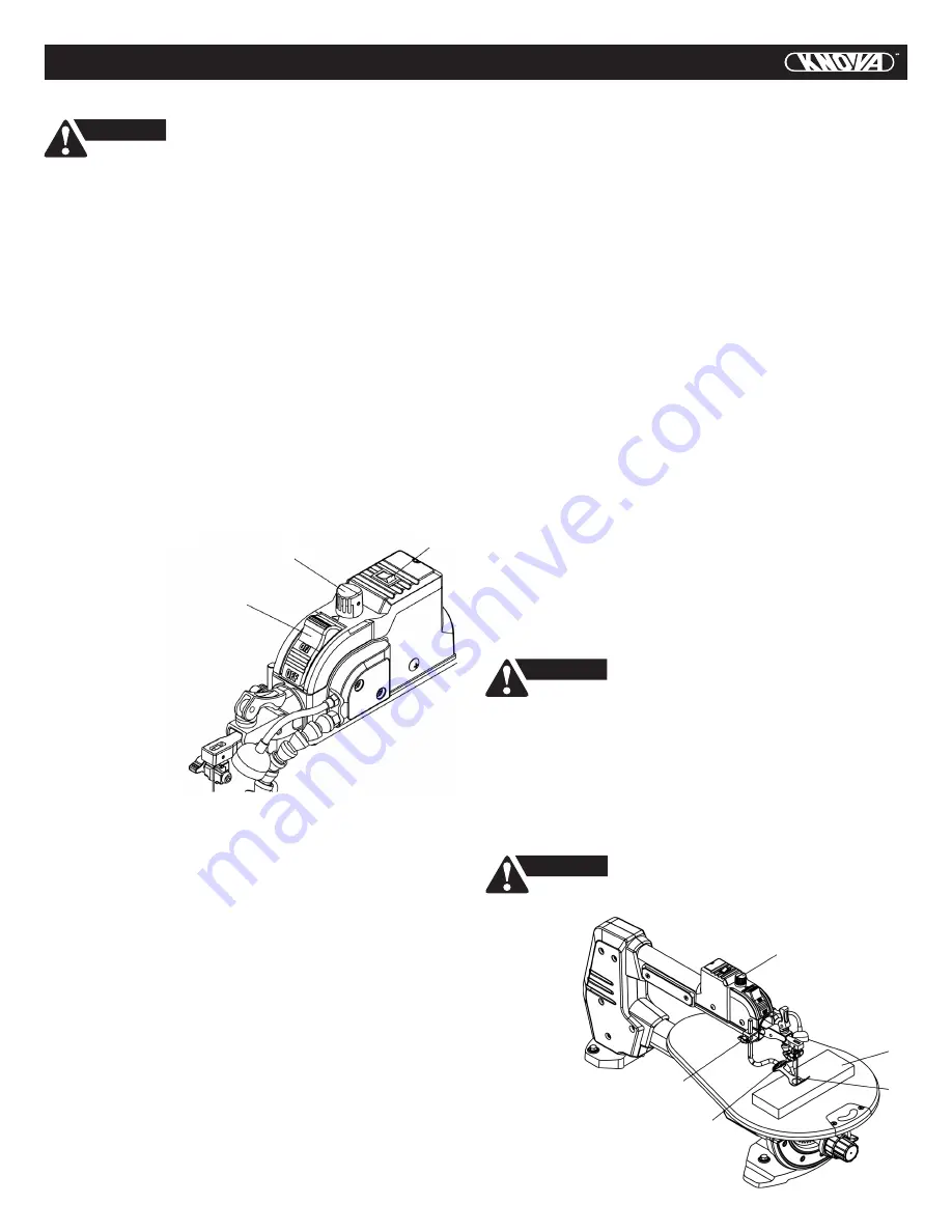
VARIABLE SPEED CONTROL AND ON/OFF SWITCH


For your own safety, always push

           the switch “OFF” when the scroll saw is not in use.

Also, in the case of power failure (all of your lights go out)

push the knob “OFF”. Remove the plug from the power

source outlet to avoid accidental starting.

CAUTION

ON/OFF SWITCH (FIG. P)

  1. To turn power ON, press on/off switch (1) to “ON”

      position.
  2. To turn power OFF, press on/off switch (1)

      to “OFF” position.

VARIABLE SPEED CONTROL KNOB (FIG. P)

The variable speed control allows greater versatility to cut a 

variety of materials such as wood, plastics, non-ferrous

metals, etc. Depending on the hardness and thickness of

material, the speed should be reduced to allow the blade 

teeth to remove cut material from the kerf.
  1. Your saw is equipped with a variable speed control

      knob (2). The blade stroke rate may be adjusted by

      simply rotating the variable speed control knob (2).
  2. Turn the speed control knob clockwise to increase

      up to 1,500 strokes per minute (SPM). Turn the speed 

      control knob counterclockwise to reduce down to

      500 strokes per minute (SPM).

WORK LIGHT (FIG. P)

  1. To turn work light on,

      press the rocker

      switch (3)

      to “ON” position.
  2. To turn work light

      off, press the rocker

      switch (3) to “OFF”

      position.

1

2

3

RECOMMENDATIONS FOR CUTTING

  1. When feeding the workpiece into the blade do not force 

      the leading edge of the workpiece into the blade because

      the it will deflect the blade, reduce the accuracy of

      cutting and possibly break the blade. Allow the saw to

      cut material by guiding the workpiece into the blade

      as it cuts.
  2. The blade teeth cut material ONLY on the down stroke.
  3. You must guide the wood into the blade slowly because

      the teeth of the blade are very small and they can only 

      remove wood when they are on the down stroke.
  4. There is a learning curve for each person who wants to

      use this saw. During that period of time it is expected

      that some blades will break until you learn how to use

      the saw and receive the greatest benefit from the blades.
  5. Best results are achieved when cutting wood less than

      one inch (25.4 mm) thick.
  6. When cutting wood thicker than one inch (25.4 mm),

      the user must guide the wood very slowly into the blade

      and take extra care not to bend or twist the blade while

      cutting in order to maximize blade life.

  7. When teeth of scroll saw blade worn out, must replace

      the new blade. Check the blade frequently for best

      cutting results. Scroll saw blades generally stay sharp

      for 1/2 to 2 hours of cutting.
  8. To get accurate cuts, be prepared to compensate for

      the blade’s tendency to follow the wood grain as you

      are cutting.
  9. This scroll saw is intended to cut wood or wood products.
10. When choosing a blade to use with your scroll saw,

      consider very fine, narrow blades to scroll cut in thin

      wood in 1/4 in. (6.4 mm) thick or less. Use wider blades

      for thicker materials but this will reduce the ability

      to cut tight curves.
11. This saw uses 5 in. (127 mm) long pin or plain end

      type blades.
12. Blades wear faster when cutting plywood or particle

      board which is very abrasive. Angle cutting in hardwoods

      reduces blade tooth set faster due to the blade deflection.

FREEHAND CUTTING (FIG. Q)

  1. Lay out desired design, or secure design to

      the workpiece (1).
  2. Raise the blade guard foot (2) by loosening the blade

      guard foot lock knob (3).
  3. Position the workpiece against the blade and place

      the blade guard foot slightly above the top surface

      of the workpiece.
  4. Secure the blade guard foot (2) by tightening the blade

      guard foot lock knob (3).
  5. Remove the workpiece from the blade before turning

      the scroll saw ON. Set the desired speed by turning the

      speed control knob (4) clockwise or counterclockwise.


In order to avoid uncontrollable lifting of

           the workpiece and to reduce blade breakage, do not

turn saw ON while the workpiece is against the blade.

CAUTION

  6. When turning the scroll saw ON, position the workpiece

      against scrap wood prior to touching the leading edge

      of the workpiece against the blade.
      

NOTE:

 For your own safety, use the scrap wood to

      perform the cutting especially for the small workpiece.
  7. Slowly feed the workpiece into the blade by guiding and 

      pressing the workpiece down against the table.

  8. When the cut is

      complete, move

      the trailing pieces

      of the workpiece

      beyond the blade

      guard foot. Turn

      the scroll saw OFF.


Do not force the leading edge of

            the workpiece into the blade, it may deflect

the blade, reduce accuracy of cutting, and possibly break

the blade.

CAUTION

4

1

2

9

3

Fig. Q

Fig. P

Summary of Contents for KN SS-18VVS

Page 1: ...Variable speed scroll saw18 Sierra caladora de velocidad variable 457 mm We invite you to read the user manual before operating your equipment Lo invitamos a leer el manual del usuario antes de opera...

Page 2: ...l hazards fire hazards or damage to the tool use proper circuit protection This tool is wired at the factory for 110 120 Volt operation It must be connected to a 110 120 Volt 15 Ampere time delay fuse...

Page 3: ...the cutting tool is unintentionally contacted 19 CHECK FOR DAMAGED PARTS Before further use of the tool a guard or other part that is damaged should be carefully checked to determine that it will oper...

Page 4: ...provides a path of least resistance for electric currents and reduces the risk of electric shock This tool is equipped with an electrical cord that has an equipment grounding conductor and a grounding...

Page 5: ...kly sets and resets the blade tension when performing interior cutting operations or changing blades SAWDUST BLOWER Keeps sawdust from covering the line of sight for more accurate cuts The best result...

Page 6: ...d compare against the list below and the illustration 2 With the help of an assistant place the saw on a secure surface and examine it carefully To avoid injury from unexpected starting or electrical...

Page 7: ...knob Blade holder lock knob Blade guard foot lock knob Blade tension lever LED work light Blade holder REAR FRONT LED work light ON OFF switch Mounting hole Sawdust blower Blade storage under table Ta...

Page 8: ...stand legs are different and cannot be mixed The two larger foot pads are marked F and must be placed on the front stand legs The two smaller foot pads are marked R and must be placed on the rear sta...

Page 9: ...ing performed on 3 4 in 19 mm or thinner material It will take slightly longer to install the blade and adjust blade tension but you will also be able to use finer blades for cutting a thinner kerf Pl...

Page 10: ...lades the hex set screws located on the upper and lower blade holders should not be over or under tightened The slot must be slightly wider than the thickness of the blade After the blade is installed...

Page 11: ...2 Fig M SAWDUST BLOWER FIG N The sawdust blower 1 should be positioned to point to the blade and workpiece to blow sawdust out of the line of sight when cutting It is not designed to blow all of the...

Page 12: ...user must guide the wood very slowly into the blade and take extra care not to bend or twist the blade while cutting in order to maximize blade life 7 When teeth of scroll saw blade worn out must rep...

Page 13: ...iece to be cut and make sure the scrap wood 6 is secure 4 Position the workpiece against the blade and place the blade guard foot 1 slightly above the top surface of the workpiece 5 Secure the blade g...

Page 14: ...able will allow the wood being cut to glide smoothly across the work surface Ball bearings in the scroll saw are packed with grease at the factory and require no further lubrication Use only mild soap...

Page 15: ...ng tension 2 Overworking blades 3 Wrong blade application 4 Twisting blade in wood 1 Blade holders not aligned 1 Defective cord or plug 2 Defective motor 3 Blown overload breaker 1 Improper mounting o...

Page 16: ...ACKET STOP 1 263T CROWN NUT M6 x 0 75 T 5 1 263W SQUARE NUT M6 x 0 75 T 5 1 27XG ROLL PIN 1 2A4U TURNTABLE 1 2E63 ROCKER SWITCH 1 2EBB CR RE COUNT HD TAPPING SCREW M5 x 12 16 2 2EBZ TURNTABLE COVER 1...

Page 17: ...SCHEMATIC B HARDWARE BAG 16 Variable speed scroll saw 18 Sierra caladora de velocidad variable 457 mm KN SS 18VVS...

Page 18: ...3EPT CAUTION LABEL 2 3EPU CAUTION LABEL 2 47MQ WARNING LABEL 1 18 IN SCROLL SAW PARTS LIST FOR STAND Description Qty I D No Size 3EXM G HARDWARE BAG 0J4W FLAT WASHER 8 2 x 18 1 5 4 0JPS HEX HD BOLT M8...

Page 19: ...18 NOTES...

Page 20: ...io pueden contener ICONOS DE ADVERTENCIAS s mbolos dibujados para alertar o instruir al usuario para que evite situaciones de riesgo La comprensi n y la observaci n de estos s mbolos lo ayudar n a man...

Page 21: ...s Se recomienda utilizar calzado antideslizante Utilice una protecci n para cubrir y contener el cabello largo 15 DESCONECTE LAS HERRAMIENTAS DE LA FUENTE DE ENERGIA antes de realizar el mantenimiento...

Page 22: ...ancar la sierra 10 LOS DIENTES DE LA SEGUETA DEBEN APUNTAR hacia abajo 11 Antes de empezar a trabajar con la sierra LA MESA DEBE ESTAR LIMPIA de cualquier residuo No realice trazados ajustes ni montaj...

Page 23: ...18 y debe estar protegido con un fusible de retardo de 1 6 A Antes de conectar el motor a la l nea de energ a el ctrica aseg rese de que el inter ruptor est en la posici n de APAGADO y de que la corri...

Page 24: ...ntren en contacto con la segueta BOT N DE BLOQUEO DEL PIE DEL GUARDASEGUETAS Permite subir o bajar el pie y bloquearlo a la altura deseada AMARRES DE LA SEGUETA Sujetan y sit an las seguetas ALMACENAM...

Page 25: ...traci n 2 Junto con un asistente coloque la sierra caladora sobre una superficie segura y exam nela cuidadosamente Para evitar lesiones por un arranque inesperado o por una descarga el ctrica no enchu...

Page 26: ...ot n de bloqueo del pie del guardaseguetas Palanca de tensi n de la segueta Luz LED de trabajo Porta seguetas TRASERO FRENTE Luz LED de trabajo Interruptor de ENCENDIDO APAGADO Hoyos de montaje Extrac...

Page 27: ...de sost n delanteras y las patas de sost n traseras son diferentes y no se pueden mezclar Dos almohadillas de pie m s grandes son marcadas con F y deben ser colocadas en las patas de sost n delanteras...

Page 28: ...r cortes delgados precisos e intrincados en material de 3 4 pulgadas 19 mm de espesor o menos El tiempo ser m s largo en el montaje de la segueta y tensi n de la segueta pero tambi n podr usar segueta...

Page 29: ...o se monten seguetas de extremo con pasador no deben apretarse de m s ni de menos los tornillos situados en los amarres superior e inferior de la segueta La ranura debe ser ligeramente m s ancha que e...

Page 30: ...o se corte en ngulo el pie del guardaseguetas 1 debe regularse de modo que quede paralelo a la mesa y descanse plano por encima de la pieza 3 2 1 Fig M 1 Para regularlo afloje el tornillo de protecci...

Page 31: ...tido contrario al de las manecillas del reloj para reducir los golpes por minuto SPM hasta 500 LUZ DE TRABAJO FIG P 1 Para encender el luz de trabajo ON presione el interruptor oscilante de encendido...

Page 32: ...romper la segueta ADVERTENCIA ADVERTENCIA 4 1 2 9 3 Fig Q CORTE EN NGULO FIG Q R S Para evitar lesiones siempre mantenga sus manos debajo de la mesa durante el funcionamiento ADVERTENCIA Corte de Bis...

Page 33: ...ulgadas 6 4 mm en la pieza de trabajo 2 Levante la palanca de tensi n de la segueta 2 y retire la cuchilla 3 Consulte la secci n de MONTAJE Y DESMONTAJE DE LA SEGUETA 3 Coloque la pieza a trabajar en...

Page 34: ...6 S3 19 Protecci n respiratoria NIOSH OSHA MSHA Una ligera capa de cera sobre la superficie de la mesa de trabajo facilitar el deslizamiento suave de la madera a cortar LUBRICACION Los rodamientos esf...

Page 35: ...so 3 Disyuntor de sobrecarga quemado 1 Montaje incorrecto de la segueta 2 Superficie de montaje inadecuada 3 Mesa suelta o mesa apoyada contra el motor 4 Montaje de motor suelto 1 Ajuste la tensi n de...

Page 36: ...ETA EN CRUZ M5 x 0 8 25 1 25ZQ ESPACIADOR 1 25ZR PARADA DEL SOPORTE 1 263T TUERCA DE CORONA M6 x 0 75 T 5 1 263W TUERCA CUADRADA M6 x 0 75 T 5 1 27XG PIVOTE DE RODILLO 1 2A4U PLACA GIRATORIA 1 2E63 IN...

Page 37: ...ESQUEMA B BOLSA DE HERRAMIENTAS 36 Variable speed scroll saw 18 Sierra caladora de velocidad variable 457 mm KN SS 18VVS...

Page 38: ...ECAUCION 2 47MQ ETIQUETA DE ADVERTENCIA 1 18 457 2 MM SIERRA DE CALADORA LISTA DE PARTES DE LA BASE Descripci n Cant No ID Medida 3EXM G BOLSA DE PARTES 0J4W ARANDELA PLANA 8 2 x 18 1 5 4 0JPS PERNO C...

Page 39: ...38 NOTAS...

Page 40: ...www knova com mx...

Reviews: