


SMY133-SMY134-SMP133 Operating Manual
6.3.2 Pulse Counters
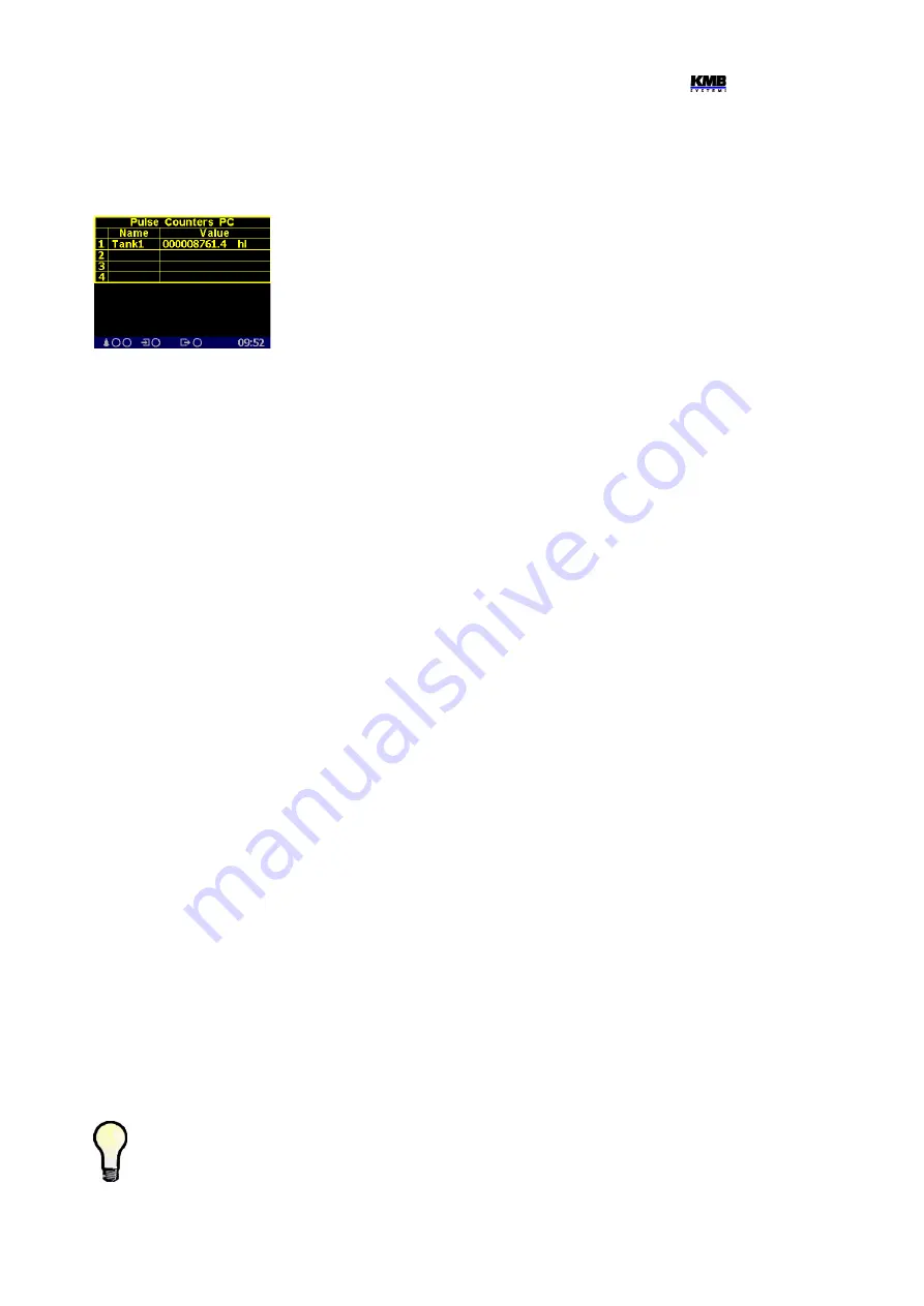
If at least one pulse counter action is used in the I/O setup the pulse
counters screen can be listed in the electricity meter branch.
The table shows set pulse counters PC corresponding to digital
inputs DI. Actual pulse counter value recalculated to preset pulse
counter quantity units is displayed in appropriate line including its
name and unit (shortened to 6/4 characters).
6.4 I/O Block Processing
The I/O block is processed periodically each measurement cycle (i.e. 200 ms @ 50 Hz), so it defines
the fastest reaction time of all set actions.
The evaluation order is as follows :
1.
Conditions
of the clauses that are not switched-off are evaluated in the order in which they
are listed – from top to bottom.
As default, individual conditions are evaluated from the left to the right. But expressions
bound with the AND-operator are always evaluated first, then that bound with the OR -
operator.
If any variable used in a condition, values from the previous I/O block evaluation cycle are
used. In the first evaluation cycle (after the instrument power-up or a restart), value of all the
variables is false, excluding that keeping true due to the
Persistent
option.
2.
Variable type actions
(of clauses that are not switched off) are evaluated from top to bottom
(the variables get new values).
3. The steps 1 and 2 executed once more with the new variable values (the conditions and
variable values are updated).
4. All of the
actions
(of the clauses that are not switched off), excluding the variable type
actions, are evaluated and executed from top to bottom, using updated conditions.
5. Updated values of the
variables
are stored for the next I/O block evaluation step.
6.4.1 Digital Inputs
6.4.1.1 Digital Input Filter
Digital inputs are read each measurement cycle (with period of 0.2 ms). For interference suppression,
the signal is filtered digitally (by firmware). Default limit frequency of the filter is preset to 100 Hz.
The filter limit frequency can be set in
Advanced
parameters.
The DI filter minimum pulse width
parameter defines minimum pulse/gap width in milliseconds. When, for example, limit frequency of
100 Hz is desired set the parameter to 50 ms (pulse 50ms + gap 50 ms = 100ms). Pulses and gaps
shorter than the set limit will be filtered.
It is not recommended to increase the limit frequency too much. Otherwise interference
spikes can cause false measurement.
On contrary, when maximum output frequency of a sensor connected to the instrument is
lower than 100Hz, it is suitable to decrease the limit frequency to corresponding value.
56
Fig. 6.32 : Pulse Counters
Screen Example


