


SMY133-SMY134-SMP133 Operating Manual
Fig. 6.19 : I/O Setup – Condition Example of the Variable Action
Then the variable is controlled by the condition and can be simply used in other clauses as another
condition
Var1
- see the chapter
I/O Conditions
below.
During the I/O block initialization after the instrument power-up or restart, all of the variables
(excluding that keeping true due to the Persistent option) are set to false. After each of the I/
O block evaluation step, variable values are stored and used in the next step. See the I/O
Block Processing chapter.
6.2.2 I/O Conditions
6.2.2.1 Digital Input Condition
Click on the
-button in the condition part of target clause and choose the
Digital Input
option.
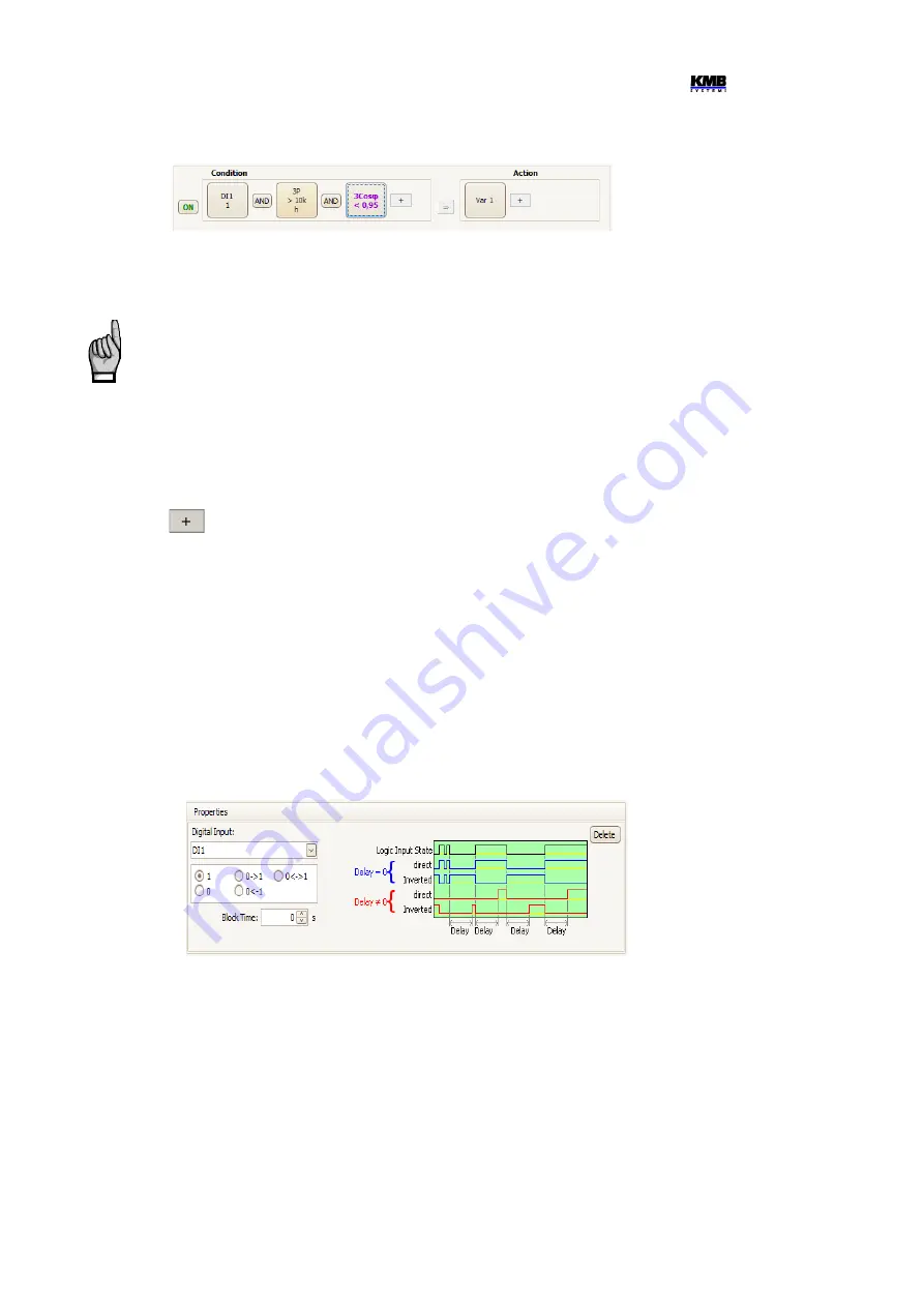
Then you must set :
•
desired
Digital Input
•
1 / 0 / 0<->1 / 1<->0 / 0<->1
… state (=level controlled mode) or state change (=slope
controlled mode) of the digital input that gets the condition
true
(logical 1).
If any of state change set and the digital input keeps the same value as in the previous I/O
block evaluation cycle the condition result is false.
•
Block Time
… minimum duration of stable digital input state (relevant for level-controlled
mode only). If not zero, quick changes of the input signal are “filtered” and new state of the
condition result occurs only if the signal lasts for at least set block time. This setup is
indicated with the “b” character in the condition icon.
Fig. 6.20 : I/O Setup – Digital Input Condition Properties
6.2.2.2 Measured Quantity Condition
Values of main measured quantities can be used as condition in the I/O setup clauses. Selected
quantity size is compared with preset limit and gets either true(1) or false(0) result. For this, the
following parameters must be preset :
•
Quantity
& P
hase
… desired control quantity (single- or three-phase or AND/OR combination
of them)
•
Actual
or A
verage
… desired value of the control quantity
•
Abs
… check if absolute value of control quantity to be evaluated (relevant for bipolar
quantities only)
52


