background image


Instruction Manual

 IDO

8065

-HILO

8065


24/08/15     Rev: 1.0.0                                                                                               (TRANSLATION OF ORIGINAL LANGUAGE) 

27 


Summary of Contents for HILO 8065

Page 1: ...RIDO8065 HILO8065 INSTRUCTION MANUAL 20084 Lacchiarella MI Italy Via della Levata 1 Tel 39 02 8929291 E mail info klinmak com www klinmak com ...

Page 2: ... TRANSLATION OF ORIGINAL LANGUAGE II In order to obtain the best results it is recommended to use original KlinMak Srl consumables The trade or registered marks mentioned in this manual belong to their respective owners ...

Page 3: ...ev 1 0 0 TRANSLATION OF ORIGINAL LANGUAGE III RIDO8065 HILO8065 INSTRUCTION MANUAL Description Ride on scrubber dryer for use in commercial industrial premises Model RIDO8065 HILO8065 Manual ongoing review 1 0 0 ...

Page 4: ...ty devices of fixed closing guards 19 4 3 Safety devices relevant to mobile guards 19 5 CE PLATE POSITION 19 6 MACHINE TRANSPORT AND LIFTING 20 7 INTENDED USE OF THE MACHINE WASHING AND DRYING PHASE 21 8 INTENDED USE OF THE MACHINE MACHINE BEING MOVED WITHOUT WASHING OR DRYING 21 9 REASONABLY FORESEEABLE INCORRECT USE OF THE MACHINE22 10 SUPPLIED KIT 23 11 INSTALLATION 24 11 1 Preliminary operatio...

Page 5: ...CH 3 36 14 3 4 BRUSH PLATE LIFTING SWITCH 4 36 14 3 5 BRUSH PRESSURE INDICATOR Only for HILO8065 5 36 14 3 6 TRAVEL DIRECTION SELECTOR 6 37 14 3 7 WATER DETERGENT SOLUTION FLOW CONTROL KNOB 7 37 14 3 8 CHEMICAL METERING CONTROL KNOB only for Ki Do supplied version 8 37 14 3 9 BATTERY CHARGE STATUS INDICATOR 9 38 14 3 10 HOUR COUNTER 10 38 14 3 11 ACOUSTIC SIGNAL 11 38 14 3 1 STABILIZING KNOB FOR M...

Page 6: ...TMENT 46 15 4 BRUSH REPLACEMENT 46 15 5 WIPER ASSEMBLY 47 15 6 WIPER ADJUSTMENT 48 15 7 WIPER DRYING BLADE REPLACEMENT 50 15 8 CLEAN WATER FILTER CLEANING 50 15 9 EXTRACTION FILTER CLEANING 51 15 10 MAINTENANCE SCHEDULE 52 15 11 SUMMARY FOR GOOD MAINTENANCE OF THE MACHINE 53 15 12 TROUBLESHOOTING 54 16 SOUND EMISSION 56 17 WIRING DIAGRAM 57 18 CE CONFORMITY 60 ...

Page 7: ... Italian Legislative Decree 17 10 the Low Voltage Directive 2014 35 CE Electromagnetic Compatibility 2014 30 CE with top quality materials and devoting a special effort to reducing the risk of accidents as much as possible We have therefore drawn up this manual in order to provide you with adequate instructions on the correct use and correct maintenance which are essential for the operator s safet...

Page 8: ...res that might cause severe personal injury or even be fatal CAUTION CAUTION Hazardous or unsafe procedures that might cause non severe personal injury or damage to the machine or surrounding objects En FOR SAFETY Used to identify actions to be undertaken for safe machine operation Before using the device for the first time read these original instructions follow them and store them for future use...

Page 9: ...e solenoid valve regulates the amount of detergent solution conveyed to the washing system The disc washing device includes two counter rotating disc brushes the electric motor the actuator to lift the entire brush unit the manual cam for lifting the wiper only and the controls The brushes wash the floor while the motor and the pair of gears solidly attached to the brushes actuate their motion The...

Page 10: ...rol the direction and speed of the machine The steering control system includes the speed pedal the steering wheel the brake pedal The speed pedal is unidirectional Depending on the setting of the running direction via the suitable panel selector the machine moves forwards or backwards With the steering wheel the operator steers the driving wheel in the desired direction Both models are equipped w...

Page 11: ...in Brush set lifting motor 0 03 kW Recovery Function Recovery tank 80 l Silenced suction turbine 3 stages 0 52 kW Suction vacuum 160 mbars Power drive Moving speed 0 6 km h 0 4 km h Operation Forwarding motor motor drive unit 0 3 kW Type of drive rear wheel with differential Max climbing ability 16 Ramp 7 continuous Minimum steering corridor 1 880 mm Power supply Power supply 24 V Number of Batter...

Page 12: ...UAGE 12 Dimensions Weights and Noise level Machine dimensions luxlaxh Inclined wiper 1 320x730x1 215 mm Machine packaging dimensions Inclined wiper 1 560x800x1 360 mm Unladen weight without batteries with package 130 160 kg Unladen weight with package 215 245 kg Noise level 66 3 dB A ...

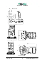
Page 13: ...Instruction Manual IDO8065 HILO8065 24 08 15 Rev 1 0 0 TRANSLATION OF ORIGINAL LANGUAGE 13 3 1 Dimensions ...

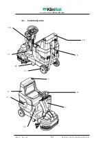
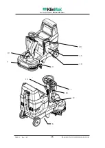
Page 14: ...Instruction Manual IDO8065 HILO8065 24 08 15 Rev 1 0 0 TRANSLATION OF ORIGINAL LANGUAGE 14 3 2 Functional units 2 3 4 5 6 11 13 14 16 17 18 22 ...

Page 15: ...Instruction Manual IDO8065 HILO8065 24 08 15 Rev 1 0 0 TRANSLATION OF ORIGINAL LANGUAGE 15 1 7 8 9 10 12 15 19 20 18 24 ...

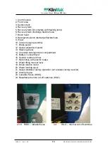
Page 16: ...Wiper 10 Vacuum engine turbine 11 Brake pedal 12 Speed adjustment pedal 13 Steering wheel 14 Chemical detergent tank compartment 15 Battery compartment 16 Suction turbine air filter 17 Motor drive with electric brake 18 Wiper lifting manual lever 19 Brush rotation motor 20 Water loading spout 21 Speed stabilizer during operation not enabled during transfer 22 Anti tip device 23 Lamellar Fuses RIDO...

Page 17: ...Do not operate the machine near flammable liquids powders or vapours The machine is designed for commercial use e g to be used inside supermarkets hotels schools hospitals factories warehouses thus for more complex applications than simple domestic cleaning operations The use of the machine must be exclusively entrusted to personnel trained and informed on correct use Maintenance and repair operat...

Page 18: ...oid contact of the acid contained in the batteries with the skin WARNING Never place any metal objects on the top part of the batteries Strictly do not wash the floor scrubber dryer with pressure washers and electrical parts with water FOR SAFETY Immediately report any machine damage or malfunctioning Do not use the machine unless it is in perfect operating conditions Carefully read the informatio...

Page 19: ...d closing guards The components that protect some areas that contain moving parts or live equipment are considered fixed closing guards The brush plate is fitted with fixed closing guard consisting in the plastic material protection casing The steering column contains moving parts levers for lifting the brush plate and live equipment electrical panel motors wiring This column is protected by a pla...

Page 20: ...ing care to lock the wheels to prevent the machine from moving Transport and any lifting must be done with the machine on a pallet It is recommended to empty the solution recovery tanks If the rubber dryer RIDO8065 HILO8065 is loaded on a vehicle with ramp or in any case every time it is required to drive it on a steep ramp it is recommended to lift the brush plate and take down the splash guards ...

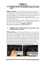
Page 21: ...5 Other operations are not intended for the RIDO8065 HILO8065 Any other operation should therefore be considered as improper 8 INTENDED USE OF THE MACHINE machine being moved without washing or drying RIDO8065 HILO8065 can be handled without brush plate lowered and brushes in contact with the floor or with the drying turbine turned off This can happen during transfer from one room to another at th...

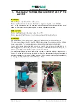
Page 22: ...NG The machine has been designed for being used on flat surfaces and small slopes The maximum slope allowed feasible uphill both during the operating and the transfer phases is equal to 7 corresponding to a ramp with an inclination of about 4 To cover the same ramp downhill you need to shift into reverse as indicated in the following pictures where the proper use is shown downhill shifted into rev...

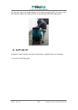
Page 23: ...or the same reason the parking brake must be always engaged when you want to leave the machine stopped on a ramp with the same placed as in the following picture 10 SUPPLIED KIT In addition to this instruction manual the machine is supplied with a kit containing 1 clean water tank filling pipe ...

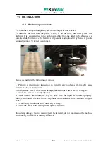
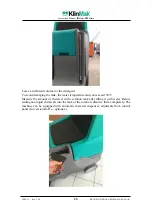
Page 24: ...x Before use perform the following operations 1 Perform a preliminary inspection to identify any problems that might cause malfunctioning or breakdowns Visually ensure there is no external damage leaks and the wheels are not damaged 3 Ensure the wiper is correctly adjusted 4 Check that the drain hose the cap the hose from the wiper are installed properly taking care to insert the hose into a sharp...

Page 25: ...the seat 2 Turn the ignition key clockwise in the ON position 3 Check the set travel direction and select it on the Forward or Backward selector 4 With operator seated and key ON the parking brake is automatically released Now slightly press the accelerator pedal and move the vehicle into the filling area by turning the steering wheel 12 2 MACHINE FILLING FOR SAFETY Before leaving the machine unat...

Page 26: ...maging the tank the water temperature must not exceed 50 C Measure the amount of chemical in the solution tank after filling it with water Before adding not liquid chemicals into the tank of the solution dissolve them completely The machine can be equipped with automatic chemical dispenser adjustable from control panel for version Ki Do optional ...

Page 27: ...Instruction Manual IDO8065 HILO8065 24 08 15 Rev 1 0 0 TRANSLATION OF ORIGINAL LANGUAGE 27 ...

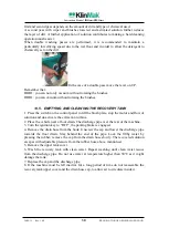
Page 28: ...king brushes the flow of solution and the brush rotation stop the machine is equipped with a solenoid valve mounted directly on the brushes plate so that when it is turned off water is feeding is stopped without unwanted dripping Water flow adjustment solenoid valve water flow manual stopping The machine is also equipped with a manual valve that stops the flow of water thus emptying the tank of th...

Page 29: ...ator pedal Brush motion and flow automatically resume when the accelerator pedal is pressed again 13 3 INTERRUPTION OF BRUSH MOTION AND WASHING 1 Press the switch that controls brush rotation on the control panel The brush motor is de activated 2 Lifting one s foot off the accelerator is also enough to stop brush rotation the machine stops and the brushes stop 3 Press the switch that controls comp...

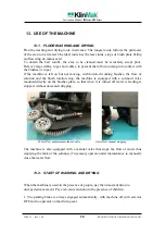
Page 30: ...trol panel to lift the brush plate stop the motor and flow of solution and de activate the extraction turbine 2 Place the vehicle near a floor drain The discharge pipe is at the rear of the machine 3 Turn the ignition key to OFF the parking brake is engaged 4 Remove the drain hose from the hook Unscrew the cap and lower the discharge pipe towards the floor drain Stay behind the end of the pipe Loc...

Page 31: ...rking brake is engaged 3 Remove the clip from the small discharge pipe connected to the solution tank The pipe is underneath the machine on the left side Lower the pipe towards the drain turn on the cock 4 Wash the tank with clean water and run clean water into the system until reaching tank capacity 80 litres Do not use water at temperature higher than 50º to clean the tank as it might be damaged...

Page 32: ...Instruction Manual IDO8065 HILO8065 24 08 15 Rev 1 0 0 TRANSLATION OF ORIGINAL LANGUAGE 32 14 CONTROL STATION 14 1 RIDO8065 CONTROL STATION 1 2 3 4 6 7 8 9 10 11 ...

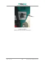
Page 33: ...Instruction Manual IDO8065 HILO8065 24 08 15 Rev 1 0 0 TRANSLATION OF ORIGINAL LANGUAGE 33 Lamellar fuses RIDO adjustment knob for maximum working speed 12 ...

Page 34: ...Instruction Manual IDO8065 HILO8065 24 08 15 Rev 1 0 0 TRANSLATION OF ORIGINAL LANGUAGE 34 14 2 HILO8065 CONTROL STATION HILO control panel 7 8 2 3 10 9 1 11 6 4 5 ...

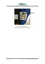
Page 35: ...Instruction Manual IDO8065 HILO8065 24 08 15 Rev 1 0 0 TRANSLATION OF ORIGINAL LANGUAGE 35 HILO circuit breakers panel adjustment knob for maximum working speed 12 ...

Page 36: ...bine To start extraction press the switch If the brush plate is lifted or the machine stops the solution flow is interrupted and the vacuum turbine is automatically disabled with a 5 second delay This delay is to allow the water recovered from the floor contained in the extraction pipe to be eliminated 14 3 4 BRUSH PLATE LIFTING SWITCH 4 For RIDO8065 The switch controls the ascent or the descent o...

Page 37: ...e speed pedal is pressed Setting it to BW BACKWARD motion will be in reverse as soon as the pedal is pressed 14 3 7 WATER DETERGENT SOLUTION FLOW CONTROL KNOB 7 The knob controls the flow in litres minute of the solution to the brush plate To increase the flow turn the solution control knob clockwise To decrease flow turn anticlockwise Adjustment ranges from 0 litres minute to 3 5 litres minute If...

Page 38: ...nce control unit activation when the washer dryer was constructed The hour counter activates at the start of brush rotation and de activates when they stop Therefore machine movement hours are actually measured 14 3 11 ACOUSTIC SIGNAL 11 The button activates the beeper 14 3 1 STABILIZING KNOB FOR MAXIMUM WORKING SPEED 12 The knob controls the maximum forward speed of the machine The recommended sp...

Page 39: ...ing operation and then when the brushes are working through the knob on the control panel next to the steering column 14 4 2 CONTROL AND PARKING BRAKE The machine is equipped with parking and control brake of the electric brake type built into the motor axle The brake is always engaged every time the machine selector is OFF and the operator is not seated on the driving seat The brake is automatica...

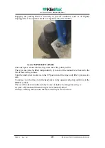
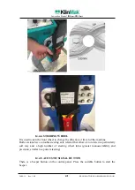
Page 40: ...tly with it The wiper may also be lifted independently by means of the manual lever located to the left of the steering column Turn the hand wheel clockwise in the UP position and the wiper only lifts by means of a cam To replace it on the floor turn the hand wheel in the opposite direction until it is on the DOWN symbol The use of this lever is indicated only in case of double cleaning processing...

Page 41: ...rection of travel of the machine Both versions have a double steering axle referral that allows it to rotate in a particularly soft way and a high number of steering wheel turns greater manoeuvrability and precision similar to a power steering 14 4 5 ACOUSTIC SIGNAL BUTTON There is a beeper button on the control panel Press the suitable button to start the beeper ...

Page 42: ...65 HILO8065 24 08 15 Rev 1 0 0 TRANSLATION OF ORIGINAL LANGUAGE 42 14 5 ELECTRICAL CONTROL DEVICES RIDO8065 HILO8065 14 5 1 MOTORS FUSE PLATE only for RIDO8065 It is located to the right of the steering column 3 4 2 1 1 2 3 4 ...

Page 43: ...o release the circuit breakers of motors which trigger following overheating deriving from an increase in electricity consumption The picture shows the functions that are protected by these devices In detail position 1 brush lifting motor thermal protection 5 Ampere position 2 brush rotation motor thermal protection 30 Ampere position 3 extraction motor thermal protection 30 Ampere position 4 main...

Page 44: ...n or if the charge status is lower than 25 Never place metal objects on top of the battery as they might cause a short circuit Replace damaged or worn cables or terminals Check the electrolyte level in each battery element before and after charging Never add acid to the batteries only use distilled water Never let the water level go below the battery plates The parts of the plates exposed to air w...

Page 45: ... a sufficient amount of water to cover the plates After completing recharge add a sufficient amount of water to bring the water level to the gauge level If the water level is too high before charging the normal electrolyte expansion may cause it to leak which causes loss of acid balancing and machine damage 5 Replace battery caps 6 Disconnect the battery connector form the machine Disconnect the b...

Page 46: ...herence to the floor By using the control panel the brush plate is fully raised or completely lowered HILO8065 The brush plate is pre shaped for optimal adherence to the floor There is the option of adjusting the brush plate pressure on the ground to have a more or less effective scrubbing action Use the panel button to do that The switch controls the pressure exerted on the floor by the brushes T...

Page 47: ...r to avoid brush or pad warping in case of no use it is recommended to always lift the wiper when the machine is idle 15 5 WIPER ASSEMBLY The machine is packed shipped and delivered with the disassembled wiper We recommend that you mount the wiper providing its rotation to the right so to have the most amount of clear hose that facilitates assembly To do this turn the mounting arm to the right mov...

Page 48: ... Two wiper adjustments are possible 1 longitudinal tilt the wiper may be tilted more forward or backward by tightening or loosening the threaded adjusting screw 2 height from ground using the clamping nut of the support wheel to move vertically the wheel itself by screwing or unscrewing it from its mounting plate ...

Page 49: ... smooth floors or ceramics lower and tilt the wiper until you have about 5 mm of the drying blade edge smoothly folded on the floor for concrete or rough floor lower and tilt the wiper until you have about 10mm of the drying blade edge smoothly folded on the floor It is recommended to lower the wiper evenly raising or lowering to the same value both the right and left wheels ...

Page 50: ...ve the fastening strap and the blade then rotate upside down or completely replace the blade 4 The same blade can be used for 4 times causing it to work every time on a different edge you should turn them every 20 working hours as a maximum 5 Fit the blade and fastening strap on the reference pins then screw the hand wheels again 6 Replace the wiper Normally the rear blade has an average service l...

Page 51: ...tly fitted onto the end of the vacuum turbine suction cone The purpose of the filter is to protect the turbine from foreign matter which might enter through the extraction cone mainly during dry extraction It is recommended to clean the filter daily To clean the filter just remove it and wash it under running water Fit it back onto the cone taking care to fit it securely onto it ...

Page 52: ...e correctly mounted x Check connections of vacuum flexible hoses x Check correct operation of brakes and steering wheel x Inspect the vacuum filter for any debris x Clean the detergent solution filter and tank Check flow x Clean brushes and check them for wear x Clean wiper rubbers and check them for wear It is recommended to turn them every 20 working hours x Clean the recovery tank and vacuum fi...

Page 53: ...witches of brushes and turbine before turning the key 5 End cleaning always clean the recovery tank dirty water 6 End cleaning always clean the drying blades 7 Wiper lever you must operate only in the case of washing without drying In all other situations never use it 8 Suction blades it is recommended to turn them when necessary bearing in mind that there are 4 useful positions 9 Brushes check fo...

Page 54: ... Poor water collection or no water collection Wiper not adjusted Adjust the wiper Wiper clogged by debris Remove debris Worn wiper blades Rotate or replace the blades Water collection flexible hose clogged Release the vacuum flexible hose Water collection flexible hose not correctly inserted in the recovery tank Reconnect the vacuum flexible hose Water collection flexible hose damaged Replace the ...

Page 55: ...ies Detergent solution flow to the floor is poor or absent Detergent solution tank empty Fill the detergent solution tank Detergent solution flow de activated or adjusted too low Activate detergent solution flow or increase the flow adjustment Detergent solution filter obstructed Clean the detergent solution filter Obstructed piping of the detergent solution system Clear the piping Detergent solut...

Page 56: ... multiple processing cycles was detected with Class 1 precision sound level meter as set out in IEC standards with constant fast slow reading both from the position where the operator is located and in positions surrounding the machine being considered The measured value of the sound pressure at the level of the operator is equal to Leq A 66 dB A ...

Page 57: ...Instruction Manual IDO8065 HILO8065 24 08 15 Rev 1 0 0 TRANSLATION OF ORIGINAL LANGUAGE 57 17 WIRING DIAGRAM RIDO8065 ...

Page 58: ...Instruction Manual IDO8065 HILO8065 24 08 15 Rev 1 0 0 TRANSLATION OF ORIGINAL LANGUAGE 58 ...

Page 59: ...Instruction Manual IDO8065 HILO8065 24 08 15 Rev 1 0 0 TRANSLATION OF ORIGINAL LANGUAGE 59 HILO8065 ...

Page 60: ...Instruction Manual IDO8065 HILO8065 24 08 15 Rev 1 0 0 TRANSLATION OF ORIGINAL LANGUAGE 60 18 CE Conformity ...

Page 61: ...dryer Type HILO 65 80 Serial number Year of manufacture complies with all relevant provisions of Directive 2006 42 EC and subsequent amendments and additions implemented in Italy by Legislative Decree 17 2010 Machinery Directive and with standards EN60335 2 72 2014 It also complies with the following directives 2014 30 EC 2014 35 EC The manufacturer also hereby declares that the technical construc...

Page 62: ...dryer Type RIDO 65 80 Serial number Year of manufacture complies with all relevant provisions of Directive 2006 42 EC and subsequent amendments and additions implemented in Italy by Legislative Decree 17 2010 Machinery Directive and with standards EN60335 2 72 2014 It also complies with the following directives 2014 30 EC 2014 35 EC The manufacturer also hereby declares that the technical construc...

Reviews: