background image


Data ultimo aggiornamento:  15/11/2013 

Pag. 11 di  28 


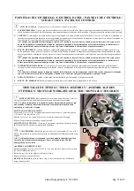
PANNELLO DI CONTROLLO / CONTROL PANEL / PANNEAU DE CONTROLE / 

SCHALTTAFEL / PANEL DE CONTROL 


CONTROL PANEL:    Control panel is composed of the following elements: 

1.


POTENTIOMETER: To regulate rotation tools speed. This potentiometer regulates the rotation speed of the tools. 

2.


HEIGHT SWITCH: The lever switch lifts and lowers the machine. This switch controls the electric actuator showed on this picture. The 
actuator is provided with limit switches that automatically switch the electrical contract when piston is on the extreme positions. (Figure 2)  

3.


RESET: Illuminated button; inverter and all peripheral units will disconnect when it is on (red). This key allows to reset the inverter. When you 
switch the machine on, a red warning light is on, to have access to the machine auxiliaries, reset the machine so green warning light will be on. 
NOTE: When red warning light is on, all auxiliaries (electrical engine and actuator) are disconnected. If red warning light is on after 
emergency key has been pressed, to reset the machine disconnect emergency key with a rotation of the red part as showed on the red 
detail itself. 

4.


STARTER: three throw switch; neutral throw, right rotation, left rotation. Planet carrier turns right by turning the switch right, planet carrier 
turns left by turning the switch left.  
NOTE: In order to stop the machine, push the emergency red button. Acting with this key the engine will stop in 1 sec, by acting with 
emergency key the machine will stop by inertia. 

5.


PILOT LIGHT: the machine is ready to work when the pilot light is on. 

6.


EMERGENCY STOP: the entire machine will shut down from the power supply by pushing this switch.   


PANNEAU DE CONTROLE:     Le panneau de contrôle est composé comme suit : 

1.


REGLEUR DE PUISSANCE : n°1, pour régler la vitesse de rotation des ustensiles. 

2.


SWITCH : n°2, interrupteur à lève pour lever et abaisser la machine, cet interrupteur commande le réalisateur électrique représenté ci-contre. 
Le réalisateur est doté d’une fin de course qui ouvre automatiquement le contact électrique quand le piston se trouve en position extrême. (Figure 2

3.


BOUTON DE RESET : n°3, bouton lumineux ; quand il est allumé (rouge) l’inverseur et tous les auxiliaires sont isolés du courant électrique  
Ce bouton permet de faire le reset de l’inverseur. Quand on allume la machine, l’espion lumineux rouge est allumé, pour pouvoir avoir accès aux 
auxiliaires de la machine, on doit faire le reset de la machine de façon à ce que l’espion lumineux vert s’allume. 

N.B. Quand l’espion lumineux rouge est allumé, tous les auxiliaires (moteur électrique, et réalisateur) sont isolés. Si l’espion rouge s’est 
allumé après avoir actionné le bouton d’urgence, il faut dèsenclenche ce dernier, grâce à une rotation du détail rouge indiqué avec les 
flèches, pour pouvoir faire le reset de la machine. 

4.


INTERRUPTEUR DE MARCHE : n°4, interrupteur à 3 positions ; position neutre, rotation à droite, rotation à gauche. en poussant 
l’interrupteur vers la droite, le porte satellites tourne en sens horaire, en le poussant vers la gauche, le porte-satellites tourne en sens anti-horaire. 
N.B.  Quand  on  veut  arrêter  la  machine  on  peut  agir  soit  avec  cet  interrupteur  soit  avec  le  bouton  rouge  d’urgence.  En  agissant  avec 
l’interrupteur de marche, le moteur s’arrête en une seconde, en agissant avec le bouton d’urgence, la machine s’arrête pour manque de 
courant. 

5.


ESPION LUMINEUX : n°5, quand il est allumé, il indique que la machine est prête pour être utilisée. 

6.


BOUTON D’URGENCE : n°6, En abaissant cet interrupteur, toute la machine est isolée du courant électrique. 


SCHALTTAFEL:   Die Schalttafel besteht aus folgenden Optionen: 

1.


POTENZIOMETER n°1, um die Geschwindigkeit und Umdrehungen der Werkzeuge zu regulieren Dieser Schalter befiehlt den elektrischen 
Bewältiger seitlich abgebildet. 
Der Bewältiger ist mit Endspur dotiert der automatisch die Stromverbindung öffnet wenn der Kolben sich auf der externen Position befindet 

2.


SWITCH


n°3, Dieser Schalter befiehlt den elektrischen Bewältiger seitlich abgebildet. 

Der Bewältiger ist mit Endspur dotiert der automatisch die Stromverbindung öffnet wenn der Kolben sich auf der externen Position befindet


3.


RESET TASTE n°3, leuchtende Taste, wenn sie an ist ( rot ) sind der Inverter und alle Sekundäre nicht am Netz verbunden. Diese Taste 
ermöglicht es das man den Inverter neu startet. Wenn man die Maschine anschaltet leuchtet die rote Kontrolllampe, um Zugriff an den 
Zuberhörteile der Maschine zu haben muss man die Reset Taste betätigen so dass die grüne Kontrolllampe angeht. 

WICHTIG: Wenn die rote  Kontrolllampe leuchtet sind alle Zubehörteile ( Elektromotor und Bewältiger ) angeschaltet. Wenn die rote 
Kontrolllampe aufleuchtet nach dem Sie die Notfalltaste betätigt haben um die Maschine neu zu starten, muss man diese mit einer 
rotation vom roten Detail, wie von den Pfeil auf dieser zeit, disinserieren. 

4.


GANGSCHALTER n°4, Schalter mit drei Positionen, neutrale Position, Umdrehung rechts, Umdrehung links. Wenn man den Schalter nach 
rechts schaltet dreht der Satellitenträger im Uhrzeigersinn, wenn man den Schalter nach links schaltet dreht der Satellitenträger im Uhrzeigersinn. 

WICHTIG: wenn man die Maschine ausschalten Mus kann man diesen Schalter oder auch die rote Notfalltaste benutzen. Mit dieser 
Taste braucht  der Motor eine Sekunde um stehen zu bleiben, mit der Notfalltaste geht die Maschine sofort komplett aus. 

5.


KONTROLLAMPE n°5, wenn sie aufleuchtet ist die Maschine funktions- bereit 

6.


NOTFALL TASTE n°6, WENN MAN DIESEN Schalter senkt wird die gesammte Maschine vom elektrischen Netz isoliert   

Summary of Contents for EXPANDER 850

Page 1: ...e to your machine or other property could occur You must receive training in the operation of this machine before operating it If you or your operator s cannot read English have this manual explanaine...

Page 2: ...Data ultimo aggiornamento 15 11 2013 Pag 2 di 28...

Page 3: ...Non permettere che sia usata come un giocattolo presta particolare attenzione se devi necessariamente usarla vicino ai bambini Non permettere che sia usata da bambini PERICOLO Spostare o modificare p...

Page 4: ...f openings and or cooling vents are blocked DO NOT put any object into the openings DO NOT use with wet hands DO NOT handle plug or appliance with wet hands WARNING Damage could occur to the machine i...

Page 5: ...i re attention si vous devez obligatoirement l utiliser pr s d enfants Ne pas permettre qu elle soit utilis e par des enfants DANGER D placer ou modifier des parties de cette machine peut causer des b...

Page 6: ...GEFAHR Das tauschen von Teilen kann zu Verletzungen oder Schaden f hren Halte H nde F e Haare Finger oder sonstige K rperteile von ffnungen und Teile in Bewegung fehrn ACHTUNG Achtung die Benutzung de...

Page 7: ...a de los ni os Non permite l empleo a los ni os PELIGRO Desplazar o modificar componentes de esta m quinq puede causar heridas y o da os Tenga manos pies cabellos dedos y cada parte del cuerpo lejos d...

Page 8: ...za e il giusto voltaggio prima di collegare la spina alla presa di corrente Controlla quanto indicato sulla targhetta di identificazione del motore Questa macchina dotata di una presa elettrica trifas...

Page 9: ...cht Anhaltung dieser Informationen befreit den Hersteller von jeder Verantwortung Jeder der die Maschine benutzt muss sich vergewissern das alle gesetzlichen Anforderungen und oder Erlaubnissen f r di...

Page 10: ...sare la macchina Questo interruttore comanda l attuatore elettrico raffigurato in Figure 2 L attuatore dotato di fine corsa che apre automaticamente il contatto elettrico quando il pistone si trova ne...

Page 11: ...d urgence il faut d senclenche ce dernier gr ce une rotation du d tail rouge indiqu avec les fl ches pour pouvoir faire le reset de la machine 4 INTERRUPTEUR DE MARCHE n 4 interrupteur 3 positions pos...

Page 12: ...TOR DE MARCHA n 4 interruptor a 3 posiciones posici n neutra rotaci n derecha rotaci n izquierda deesplazando el interruptor a la derecha el portasatelite gira en sentido horario desplazando el interr...

Page 13: ...chnet bereinander Stimmen Falls die farfalla nicht richtig positioniert ist rotieren Sie es bis es geht Mit Hilfe des Schl ssels die farfalla raus ziehen und um 90 rotieren so das sie sich in den Sitz...

Page 14: ...ttuare le operazioni di seguito descritte si deve staccare la presa di corrente dalla rete di distribuzione PULIZIA DELLA MACCHINA Bench la macchina sigillata ermeticamente si sconsiglia il lavaggio d...

Page 15: ...agujeros de inspecci n Efectuar los siguientes lubrificaci n cada 100 horas de trabajo LA MACCHINA NON FUNZIONA IF THE MACHINE DOES NOT WORK LA MACHINE NE FUNCTION PAS DIE MASCHINE FUNKTIONIERT NICHT...

Page 16: ...lavoro pulire i filtri H della scatola inverter WARNING every 200 hours of work clean the filters H of the inverter box AVERTISSEMENT chaques 200 heures de travail nettoyer les filtres H de la bo te...

Page 17: ...6 MOT180 MOT243 MOTORE 15KW 20HP MOTORE 18KW 25HP 1 17 TE9203 KIT CARRELLO POSTERIORE EXP 850 1 7 MOT118 ATTUATORE LINEARE CORSA 100 1 18 TE38001 PEDALINA 850 950 1 8 CM020801 KIT INVERTER 18 KW 850 9...

Page 18: ...TOIO 1 14 SE3701 KIT RUBINETTO EXP 1 6 SE0301 SERBATOIO EXP CPL 1 16 MAN080 PUFFER PARACOLPI M8X30 H17 2 9 TE9002 GRUPPO BANDIERA 750 850 1 KIT SERBATOIO EXP CPL Cod SE0301 N Codice Descrizione Q t 1...

Page 19: ...TA TELAIO EXP 850 Cod TE8202 N Codice Descrizione Quant 1 TE28901 SUPPORTO RUOTA ANTERIORE 850 1 2 RTO004 RUOTA ANTERIORE 1 3 ROSETTA M10 UNI6592 8 4 VITE UNI 5739 M10X25 4 5 DADO M10 DIN 985 AUTOBLOC...

Page 20: ...GER 100 UNI 7437 1 17 ANELLO SEEGER 180 UNI 7437 FORO 1 18 RD06803 BOCCOLA INTERFACCIA 2 19 RD07002 PERNO INTERFACCIA TELAIO 2 20 RD07701 INTERFACCIA SISTEMA AMMORTIZZANTE 1 21 VITE TCEI M8X30 UNI 593...

Page 21: ...1 RD27001 PROLUNGA PER INGRASSINO 1 2 PL375023 SUPPORTO BRACCI EXP750 850 1 3 PL41201 RUOTA CONICA M4 Z25 SPIROIDALE DX 1 4 PL37701 BASE CUSCINETTO 1 5 PL37603 COPERCHIO 1 6 VITE TCEI M12X25 UNI5931...

Page 22: ...OR 2450 2 20 PL38002 COPERTURA PARAOLIO 1 21 PL38101 DISTANZIALE PER PARAOLIO 1 22 RONDELLA DI SPESSORAMENTO DIN988 30X42 S 0 1 1 23 RONDELLA DI SPESSORAMENTO DIN988 30X42 S 0 2 1 24 RONDELLA DI SPESS...

Page 23: ...IZZANTE 1 2 TE01102 ASTA FILETTATA SITEMA AMMORTIZZANTE 1 3 DADO M14 UNI 5588 2 4 TE01902 SUPPOTO MOLLA 2 5 MOL007 MOLLA SISTEMA AMMORTIZZANTE 2 6 TE02902 TAPPO SISTEMA AMMORTIZZANTE 1 7 VITE M10 X 15...

Page 24: ...nf Exp 850 950 Cod TE011501 N Codice Descrizione Quant 1 TE37901 BASE REGOLAZIONE MANICO RINF 950 1 2 VITE TSEI M10X45 UNI 5933 6 3 DADO M10 DIN 985 AUTOBLOCCANTE 6 4 ROSETTA M10 UNI6592 6 5 TE05301 D...

Page 25: ...UICK ATTACK PAD HOLDER FOR PAVELUX AND DIAMOND RESIN DISKS 240 QUICK ATTACK Cod PL28001 TRASCINATORE PER TRAPEZIOIDI 240 QUICK ATTACK PAD HOLDER FOR TRAPEZIOIDI 240 QUICK ATTAC Cod UT43401 TRASCINATOR...

Page 26: ...Data ultimo aggiornamento 15 11 2013 Pag 26 di 28...

Page 27: ...ectives Es conforme a las siguientes Directivas Esta conforme as seguintes Diretivas Direttiva Macchine 2006 42 CE e successive modifiche Direttiva Bassa Tensione 2006 95 CE e successive modifiche Dir...

Page 28: ...machine est utilis e pour emplois diff rents de ceux indiqu s dans ce livret La garantie est tendue seulement aux parties originales pour l utilisation du produit Les parties normales de consommation...

Reviews: