


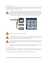


Connection to a RS-485 Network
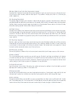
The digital interface can be connected to a 2-wire RS-485 network as shown below.
The slaves and master may be a SGR pyrgeometer or other devices. If a SGR pyrgeometer is the last device on the network a
line terminator (LT), consisting of a 120 Ω or 150 Ω resistor, must be connected between terminals A/A
'
/- and B/B
'
/+. Never
place this line termination on the derivation cable. It is also required to install the pull up and pull down resistors as shown.
The value of these resistors must be between 650 Ω and 850 Ω.
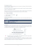
2.3.3 Analogue voltage output
The SGR-V (voltage output versions) have been factory set such that an output of 0 Volts represents 0 W/m² (this will never be
reached in practice), and the full-scale output of 1 Volt represents 1000 W/m².
The voltage output range in W/m² can be changed by the user with the supplied PC software. The maximum recommended
irradiance for all SGR pyrgeometers is 1000 W/m².
The default setting 0 to 1 Volt represents 0 to 1000 W/m².
The downward atmospheric long-wave radiation (
L
d↓
) for the default setting can be simply calculated as shown below.
L
d↓
= Downward atmospheric long-wave radiation
[W/m²]
V = Output of radiometer
[Volt]
If the pyrgeometer is used in atmospheric conditions it is advised to keep the range as factory default.
Slave 1
Slave n
Master
Common
Balanced pair
LT
LT
Pull down
Pull up
5 V
L
d↓
= (V x 1000)
17


