


2.3 Electrical connections
The SGR pyrgeometers can be supplied with a waterproof connector pre-wired to 10 m of high quality yellow cable with 8 wires
and a shield covered with a black sleeve. Longer cables are available as options. The colour code of the wires and the connector
pin numbers are shown below and on the instruction sheet.
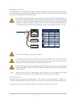
Special attention is needed to prevent power or ground loops when connecting the SGR to multiple readout devices.
Connecting the RS-485 to a grounded circuit and the analogue output to a floating circuit can cause unacceptable
ground loops. This may cause differential voltages outside the SGR specifications and will damage the unit. We
recommend using either the analogue or the digital output but not both. The maximum differential between either
of the Modbus® RS-485 lines (yellow and grey) and the power ground / RS-485 common line (black) is 70 VDC.
First connect all wires before plugging into the radiometer
The shield of the cable is connected to the aluminium radiometer housing through the connector body. Preferably,
secure the radiometer with its levelling screws on a metal support with a good connection to ground (e.g. by using
a lightning conductor) and do not connect the cable shield at the readout end.
If there is no good ground connection at the pyrgeometer, the shield at the cable end should be connected to ground
at the readout equipment. Lightning can induce high voltages in the shield but these will be led off at the pyrgeometer
or readout equipment.
Note
Long cables may be used, but the cable resistance must be smaller than 0.1 % of the impedance of the readout
equipment for the analogue outputs and may affect the baud rate of the RS-485 digital connection.
2.3.1 Power connection
The minimum power supply voltage for SGR pyrgeometers is 5 VDC. However, for optimal performance it is advised to use
12 VDC, especially when long cables are used. 5-volt power can only be used in combination with a short cable, maximum 10 m.
It is advised to protect the output of the power supply with a fast blowing fuse of maximum 250 mA rating.
Radiometer Connection
Wire
Function
Connect with
Red
Blue
Housing
Shield
Not connected
None
Modbus® common / Ground
Analogue out
V+/4-20 mA(+)
Analogue ground V-/4-20 mA(-)
Modbus® RS-485
Modbus® RS-485
Power 5 to 30 VDC
(12 V recommended)
Power ground / RS-485 Common
Ground *
White
Black
Yellow
Brown
Green
Grey
5
1
2
8
7
* Connect to ground if radiometer not grounded
4
6
3
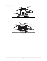
SGR-V or SGR-A
5 to 30 VDC
power supply
Modbus® RS-485
V / mA
0.0
0.2
0.4
0.6
0.8
1.0
15


