


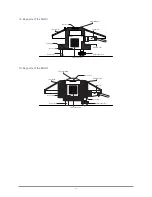


SGR-V or SGR-A
h
>10 x h
Ø5.2 mm (2x)
65 mm
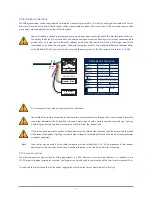
max. 100 m
5 to 30 VDC
power supply
Modbus® RS-485
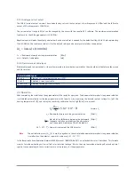
V / mA
0.0
0.2
0.4
0.6
0.8
1.0
Pyrgeometer installation
Step 1. Location
Ideally the site for the pyrgeometer should be free from any obstructions to the horizon above the plane of the sensing element. If
this is not possible, the site should be chosen in such a way that any obstruction over the azimuth range should have an elevation
not exceeding 10°. In particular, no sources of heat (such as ventilation / heating outlets) should be within the field of view.
Step 2. Mounting
The SGR pyrgeometer is provided with two holes for 5 mm bolts. Two each of stainless steel bolts, washers, nuts and nylon insulation
rings are provided in the fixing kit. The pyrgeometer should first be secured lightly with the bolts to a solid and stable mounting stand
or platform. After in recalibration the nylon insulators must be replaced with new ones to prevent corrosion.
The mounting stand temperature can vary over a wider range than the air temperature. Temperature fluctuations of the pyrgeometer
body can produce offset signals, therefore it is recommended to isolate the pyrgeometer thermally from the mounting stand by
placing it on its levelling screws. Ensure that there is a good electrical contact with earth to conduct away currents in the cable
shield induced by lightning.
Note
After recalibration and/or reinstallation the nylon insulators must be replaced with new ones to maintain durability.
Step 3. Orientation
In principle no special orientation of the instrument is required, although the World Meteorological Organisation (WMO)
recommends that the signal lead is pointed towards the nearest pole, to minimise heating of the electrical connections.
Step 4. Level pyrgeometer
Accurate measurement of the global radiation requires proper levelling of the thermopile surface. Level the instrument by turning
the two levelling screws to bring the bubble of the spirit level centrally within the marked ring. For easy levelling, first use the
screw nearest to the spirit level. When the SGR4 pyrgeometer is placed horizontally using the bubble level, or when it is mounted
with its base directly on a horizontal plane, the thermopile is horizontal within 0.1°. For the SGR3 this is 0.2°.
12


