Step 2:
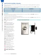
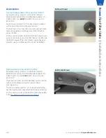
If using potentiometer/manual adjustment, rotate the potentiometer (POT/DIAL) dial on the outside of the box with a
screwdriver until the test point voltage is achieved.
NOTE:
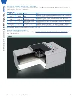
ECM Speed Controllers have 2 modes: manual adjust and BAS (Building Automation System). Standard manual
control outputs are shown below:
Measurement Tab Voltage
Motor Control
0 - 1 VDC
Off
1 - 4.5 VDC
0-100%
4.5 - 5 VDC
100%
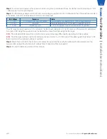
The speed controller will automatically ignore the potentiometer (POT/DIAL) when a BAS signal is detected (BAS Input Signal
>1).
VDC equations are for potentiometer (POT/DIAL) manual adjustment only (0-1 BAS input signal). The VDC equations are
based on a 1-5 Volt scale. The BAS input voltage is a 2-10 VDC scale, and therefore VDC calculated for a given CFM using
the equation must be doubled to achieve that CFM using the BAS input.
BAS Voltage
Response
Notes
0 - 1 VDC
Local control mode using push buttons
Local setpoint can be adjusted from 0 - 100% using push buttons
1 - 2 VDC
Motor Off
Recommended sending a 1.5 VDC signal to command motor off
2 - 10 VDC
Modulating Control
2 - 10 VDC modulates motor in accordance with VDC equations
Example:
If using a BAS signal, to calculate appropriate starting voltage, first calculate the VDC (as shown in above example)
VDC = 2.44 V
Then double this value
BAS Input Voltage = VDC*2
BAS Input Voltage = 2.44*2
BAS Input Voltage =
4.88V
Step 3:
Wait a few seconds for the ECM motor to adjust its speed and then verify fan airflow with measurements at the unit face
using a flow hood. Adjust the POT/DIAL, or BAS input signal to reach desired airflow as required.
Step 4:
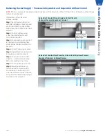
Proceed to balancing section of this manual.
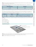
Potentiometer/Dial Adjust
Green Status LED must be blinking.
(Code 1 thru 4)
Speed Controller Adjustment
For more information visit
KeystoneCleanAir.com
v001
9
Kr
own
Fan Filter Units |
Installation Instructions


