Speed Controller Installation & Operation
Refer to Factory Label to determine which speed controller is on the unit and use the following tableto find the appropriate
installation instructions.
Sample line string:
Krown-X-X//I/SUPPLY/24/48//RSR/HEPA/FC/ECM/115/CF/R+TMB/FL+ML+BACnet/
BFC
/TC/DSW-
115//ASSP///WPF/PL-AL/F-AL/PL-B12/F-B12
Speed Controller
Page Reference
PSCSC/WK
4
ECMSC
5
BFC
8
PSCSC/WK
Sample line string:
Krown-X-X//I/SUPPLY/24/48//RSR/HEPA/FC/PSC/115//R+TMB/FL+ML/
PSC-WK
/TC/DSW-115//
ASSP///WPF/PL-AL/F-AL/PL-B12/F-B12
If unit does not have the wall kit (WK) option, proceed to step 4.
Sample line string: Krown-X-X//
I/SUPPLY/24/48//RSR/HEPA/FC/PSC/115//R+TMB/FL+ML/
PSCSC
/TC/DSW-115/PC-115/
ASSP///WPF/PL-AL/F-AL/PL-B12/F-B12
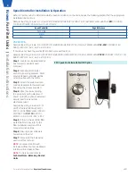
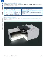
PSC Speed Controller with Wall Kit Option
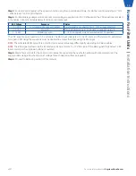
Step 1:
Locate pre-installed electric
box for wall-mounted speed
controller.
Step 2:
Wire speed controller
according to wiring diagram. Wall-
mounted speed controller will be
wired in series with the motor.
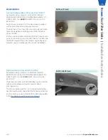
Step 3:
Attach the wall-mounted
controls faceplate to the electrical
box using the screws provided.
Step 4:
Wire the unit according
to appropriate wiring diagram. If
Power Cord (PC) option is selected,
simply insert plug end into
electrical socket.
Sample line string: Krown-X-X//
I/
SUPPLY/24/48//RSR/HEPA/FC/
PSC/115//R+TMB/FL+ML/PSCSC/
TC/DSW-115/
PC-115
/ASSP///
WPF/PL-AL/F-AL/PL-B12/F-B12
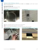
Step 5:
If the unit has an RSR filter
install the filter now, refer to the
filter installation section of this
manual for instructions.
Step 6:
Ensure proper voltage is
hooked up to the unit.
Step 7:
Proceed to the balancing
section of this manual.
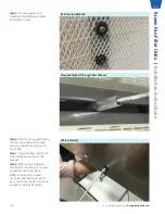
NOTE:
Clockwise rotation will
increase airflow, counter-clockwise
rotation will decrease airflow.
NOTE:
If unit is ducted, refer to
Technical Note: Balancing Ducted
Units
.
For more information visit
KeystoneCleanAir.com
v001
6
Kr
own
Fan Filter Units |
Installation Instructions


