background image

Table of Contents

Contents-1

U3042AE16

Introduction . . . . . . . . . . . . . . . . . . . . . . . . . . . . . . . . . . . . . . . . . . . . . . . . . . . . . . . . . . . . . . . . . . . . . 2
Description  . . . . . . . . . . . . . . . . . . . . . . . . . . . . . . . . . . . . . . . . . . . . . . . . . . . . . . . . . . . . . . . . . . . . . 4

Verifying the Shipment  . . . . . . . . . . . . . . . . . . . . . . . . . . . . . . . . . . . . . . . . . . . . . . . . . . . . . . . . . . 4
Network Analyzer Requirements . . . . . . . . . . . . . . . . . . . . . . . . . . . . . . . . . . . . . . . . . . . . . . . . . . . 5

Available Options  . . . . . . . . . . . . . . . . . . . . . . . . . . . . . . . . . . . . . . . . . . . . . . . . . . . . . . . . . . . . . . . . 6

Test Set Options. . . . . . . . . . . . . . . . . . . . . . . . . . . . . . . . . . . . . . . . . . . . . . . . . . . . . . . . . . . . . . . . 6
Rack Mounting Kits . . . . . . . . . . . . . . . . . . . . . . . . . . . . . . . . . . . . . . . . . . . . . . . . . . . . . . . . . . . . . 6
Network Analyzer Interface Kit Options  . . . . . . . . . . . . . . . . . . . . . . . . . . . . . . . . . . . . . . . . . . . . . 6

General Specifications. . . . . . . . . . . . . . . . . . . . . . . . . . . . . . . . . . . . . . . . . . . . . . . . . . . . . . . . . . . . . 7

Power Requirements . . . . . . . . . . . . . . . . . . . . . . . . . . . . . . . . . . . . . . . . . . . . . . . . . . . . . . . . . . . . 7
Environmental Requirements  . . . . . . . . . . . . . . . . . . . . . . . . . . . . . . . . . . . . . . . . . . . . . . . . . . . . . 8

Equipment Heating and Cooling . . . . . . . . . . . . . . . . . . . . . . . . . . . . . . . . . . . . . . . . . . . . . . . . . 8
Required Conditions for Accuracy Enhanced Measurement  . . . . . . . . . . . . . . . . . . . . . . . . . . . 8
Dimensions and Space Requirements   . . . . . . . . . . . . . . . . . . . . . . . . . . . . . . . . . . . . . . . . . . . . 8

Frequency Range and Power Levels . . . . . . . . . . . . . . . . . . . . . . . . . . . . . . . . . . . . . . . . . . . . . . . . 8
Typical Reflection Tracking . . . . . . . . . . . . . . . . . . . . . . . . . . . . . . . . . . . . . . . . . . . . . . . . . . . . . . 10

Front and Rear Panel Features . . . . . . . . . . . . . . . . . . . . . . . . . . . . . . . . . . . . . . . . . . . . . . . . . . . . . 11
Hardware Lock-link Installation (U3021-60004) . . . . . . . . . . . . . . . . . . . . . . . . . . . . . . . . . . . . . . . 14

Locking the Test Set to the PNA-L  . . . . . . . . . . . . . . . . . . . . . . . . . . . . . . . . . . . . . . . . . . . . . . . . 14

Hardware Lock-link Installation (U3021-60005) . . . . . . . . . . . . . . . . . . . . . . . . . . . . . . . . . . . . . . . 17

Locking the Test Set to the PNA or PNA-X . . . . . . . . . . . . . . . . . . . . . . . . . . . . . . . . . . . . . . . . . . 17

N5232A/B RF Interface Cable Connections (U3021-60075)   . . . . . . . . . . . . . . . . . . . . . . . . . . . . . 20

Cable Connection Procedure. . . . . . . . . . . . . . . . . . . . . . . . . . . . . . . . . . . . . . . . . . . . . . . . . . . . . 20

N5222A/42A/B RF Interface Cable Connections (U3021-60077)    . . . . . . . . . . . . . . . . . . . . . . . . . 22

Cable Connection Procedure. . . . . . . . . . . . . . . . . . . . . . . . . . . . . . . . . . . . . . . . . . . . . . . . . . . . . 22

Test Set I/O Cable Installation  . . . . . . . . . . . . . . . . . . . . . . . . . . . . . . . . . . . . . . . . . . . . . . . . . . . . . 24

Interconnect Cable Verification . . . . . . . . . . . . . . . . . . . . . . . . . . . . . . . . . . . . . . . . . . . . . . . . . . . 24

System Operational Check . . . . . . . . . . . . . . . . . . . . . . . . . . . . . . . . . . . . . . . . . . . . . . . . . . . . . . . . 25

Equipment Setup . . . . . . . . . . . . . . . . . . . . . . . . . . . . . . . . . . . . . . . . . . . . . . . . . . . . . . . . . . . . . . 25
Verify Results . . . . . . . . . . . . . . . . . . . . . . . . . . . . . . . . . . . . . . . . . . . . . . . . . . . . . . . . . . . . . . . . . 26

Controlling the Test Set with N5222/32/42A/B  .  .  .  .  .  .  .  .  .  .  .  .  .  . . . . . . . . . . . . . . . . . . . . . . . 31

Typeface Key Conventions. . . . . . . . . . . . . . . . . . . . . . . . . . . . . . . . . . . . . . . . . . . . . . . . . . . . . . . 31

Multiport Mode for Option 551 . . . . . . . . . . . . . . . . . . . . . . . . . . . . . . . . . . . . . . . . . . . . . . . . . . . 3

3

How to Access Multiport Mode . . . . . . . . . . . . . . . . . . . . . . . . . . . . . . . . . . . . . . . . . . . . . . . . . 3

3

External Test Set Control Feature . . . . . . . . . . . . . . . . . . . . . . . . . . . . . . . . . . . . . . . . . . . . . . . 3

4

Trace Measure S-Parameter  . . . . . . . . . . . . . . . . . . . . . . . . . . . . . . . . . . . . . . . . . . . . . . . . . . . 3

5

New Trace Measure S-Parameter . . . . . . . . . . . . . . . . . . . . . . . . . . . . . . . . . . . . . . . . . . . . . . . 3

5

Balanced Tab: . . . . . . . . . . . . . . . . . . . . . . . . . . . . . . . . . . . . . . . . . . . . . . . . . . . . . . . . . . . . . . . 3

6

Receivers Tab:. . . . . . . . . . . . . . . . . . . . . . . . . . . . . . . . . . . . . . . . . . . . . . . . . . . . . . . . . . . . . . . 3

6

RF Path Configuration with Option 029 . . . . . . . . . . . . . . . . . . . . . . . . . . . . . . . . . . . . . . . . . . . 3

7

N-Port Calibration  . . . . . . . . . . . . . . . . . . . . . . . . . . . . . . . . . . . . . . . . . . . . . . . . . . . . . . . . . . . 3

8

Interface Control  . . . . . . . . . . . . . . . . . . . . . . . . . . . . . . . . . . . . . . . . . . . . . . . . . . . . . . . . . . . . . . 

40

Overview of the Interface Control  . . . . . . . . . . . . . . . . . . . . . . . . . . . . . . . . . . . . . . . . . . . . . . . 

40

How to Access Interface Control Settings  . . . . . . . . . . . . . . . . . . . . . . . . . . . . . . . . . . . . . . . . 4

1

Using Interface Control Mode  . . . . . . . . . . . . . . . . . . . . . . . . . . . . . . . . . . . . . . . . . . . . . . . . . . 4

2

SCPI Control Mode. . . . . . . . . . . . . . . . . . . . . . . . . . . . . . . . . . . . . . . . . . . . . . . . . . . . . . . . . . . . . 4

4

Overview of the SCPI Control  . . . . . . . . . . . . . . . . . . . . . . . . . . . . . . . . . . . . . . . . . . . . . . . . . . 4

4

How to Access the Command Processor . . . . . . . . . . . . . . . . . . . . . . . . . . . . . . . . . . . . . . . . . 4

4

SCPI Command Processor Console . . . . . . . . . . . . . . . . . . . . . . . . . . . . . . . . . . . . . . . . . . . . . . 4

5

Measurement Application Note. . . . . . . . . . . . . . . . . . . . . . . . . . . . . . . . . . . . . . . . . . . . . . . . . . . . 4

Sweep Setup for Multiport and Standalaone Modes 

. . . . . . . . . . . . . . . . . . . . . . . . . . . . . . . . . . 3

1

Summary of Contents for U3042AE16

Page 1: ...Keysight Technologies U3042AE16 Multiport Test Set Extension User s and Service Guide...

Page 2: ...r software or commercial computer software documentation No additional government requirements beyond those set forth in the EULA shall apply except to the extent that those terms rights or licenses a...

Page 3: ...1 60075 20 Cable Connection Procedure 20 N5222A 42A B RF Interface Cable Connections U3021 60077 22 Cable Connection Procedure 22 Test Set I O Cable Installation 24 Interconnect Cable Verification 24...

Page 4: ...eck 62 Service Information 63 Replaceable Parts 63 System Block Diagrams 65 Theory of Operation 66 RF Coupler Bridges 66 RF Switch Components 66 Troubleshooting the Test Set 67 Electrostatic Discharge...

Page 5: ...U3042AE16 User s and Service Guide U3042 90012 1...

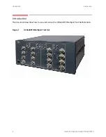
Page 6: ...3042AE16 Introduction Introduction This document describes how to use and service the U3042AE16 Multiport Test Set Extension Figure 1 U3042AE16 Multiport Test Set 2 User s and Service Guide U3042 9001...

Page 7: ...U3042AE16 Introduction Figure 2 4 Port N5242B PNA X with U3042AE16 Figure 3 4 Port N5232A PNA L with U3042AE16 User s and Service Guide U3042 90012 3...

Page 8: ...as the PNA PNA L and PNA X Analyzer refers to all series of PNA PNA L and PNA X The U3042AE16 will be referred to as the test set The B Model analyzers have the darker Keysight color format The Test...

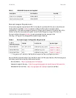
Page 9: ...wing web site links provide the necessary information needed Documentation http www keysight com find pna Network Analyzer Firmware http na support keysight com pna firmware firmware htm U3042AE16 Tes...

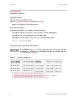
Page 10: ...kits to interface the test set with your analyzer The interface kit model option includes the hardware lock link and cable kit listed in Table 3 Table 3 Interface Kit Options 20 Port Network Analyzer...

Page 11: ...es 6 or 7 on page 10 can be subtracted from the analyzers dynamic range to determine the approximate performance of the system CAUTION This product is designed for use in Installation Category II and...

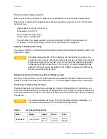
Page 12: ...maximum operating temperature of the instrument by 4 C for every 100 watts dissipated in the cabinet If the total power dissipated in the cabinet is greater than 800 watts forced convection must be us...

Page 13: ...um level to ensure no damage Do not apply any DC voltage to the Access or Test Set ports Refer to your analyzer s specifications to determine the maximum input power levels for the access and test por...

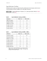
Page 14: ...MHz 4 10 50 MHz to 500 MHz 5 11 500 MHz to 3 2 GHz 7 13 3 2 GHz to 10 GHz 12 18 10 GHz to 16 GHz 15 24 16 GHz to 20 GHz 17 28 Table 7 Typical Reflection Tracking with PNA or PNA X Frequency Ports 1 t...

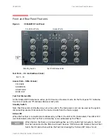
Page 15: ...witch Note that this switch is Standby only not a line switch The main power cord can be used as the system disconnecting device It disconnects the mains circuits from the mains supply Active LED When...

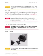
Page 16: ...e network analyzer Line Module The line fuse as well as a spare reside within the line module Figure 6 illustrates where the fuses are located and how to access them Install the instrument so that the...

Page 17: ...t com for assistance in power cord selection The detachable power cord is the instrument disconnecting device It disconnects the mains circuits from the mains supply before other parts of the instrume...

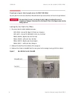
Page 18: ...ed Locking the Test Set to the PNA L 1 The lock link kit U3021 60004 includes 0515 1619 Screw T20 M4x0 7 25 mm x2 Analyzer 0515 2317 Screw T15 M3 5x0 6 12 mm x2 Test Set N5242 20208 Right Lock link Te...

Page 19: ...r 5 Remove the two upper standoffs from the rear panel of the test set using a T20 torx driver 6 Install the left and right lock links onto the test set as shown in Figure 9 Figure 9 Install Lock link...

Page 20: ...k links using the spring loaded screw If the analyzer s lock links are not aligned with the screw holes loosen the screws securing the feet to the instrument to align and tighten Figure 11 Secure and...

Page 21: ...opened Locking the Test Set to the PNA or PNA X 1 The lock link kit U3021 60005 includes 0515 1619 Screw T20 M4x0 7 25 mm x2 Analyzer 0515 2317 Screw T15 M3 5x0 6 12 mm x2 Test Set 5023 0132 Lock lin...

Page 22: ...r standoffs from the rear panel of the test set using a T20 Torx driver 6 Install the left and right lock links onto the test set as shown in Figure 14 Figure 14 Install Lock links onto the Test Set R...

Page 23: ...links to the test set upper locking feet using the spring loaded screws If the analyzer s lower lock links are not aligned with the screw holes loosen the screws securing the feet to the instrument t...

Page 24: ...NA L Interface Cable Connection U3021 60075 Numeric Order RF Cables From PNA L To Test Set 1 U3042 20182 Port 1 SOURCE OUT Port 5 SOURCE IN 2 U3042 20183 Port 1 CPLR THRU Port 5 CPLR THRU 3 U3042 2018...

Page 25: ...cable N4011 21002 to the Test Set Interface connector on the rear panel similar Figure 19 on page 24 Refer to System Operational Check on page 25 for turn on verification of the multiport system 84 83...

Page 26: ...onnect Cable Verification on page 24 Table 9 PNA or PNA X RF Interface Cable Connection U3021 60077 Numeric Order RF Cables From PNA X To Test Set 1 U3042 20122 Port 1 CPLR THRU Port 5 CPLR THRU 2 U30...

Page 27: ...3042 20119 The cables must be connected in the numeric order listed in Table 9 on page 22 Figure 18 PNA X RF Interface Cable Connections 19 21 23 23 23 23 25 27 28 20 22 24 24 24 24 Continue to Test S...

Page 28: ...r panel similar to Figure 19 Figure 19 Test Set I O Cable Connection Interconnect Cable Verification 1 Perform the System Operational Check on page 25 2 If the problem still exists perform the RF Swit...

Page 29: ...s procedure Stack the analyzer on top of the test set Install the Test Set I O cable on the rear panel Install all of the RF interface cables on the front panel Install the included female 3 5 mm shor...

Page 30: ...with this signal path for proper installation The trace ripple peak peak variation is normal for this raw uncorrected measurement Table 10 Reflection Response Results Reflection Port Response Trace C...

Page 31: ...rt 13 Port 5 SOURCE SIGNAL RCVR SIGNAL S1 S2 1 S9 4 3 2 1 C Port 17 3 4 2 1 2 3 4 C C S10 4 3 2 1 C Port 10 Port 14 Port 6 S3 S4 3 S11 4 3 2 1 C Port 18 1 2 4 1 2 3 4 C C S12 4 3 2 1 C Port 11 Port 15...

Page 32: ...OUT CPLR ARM Port 9 Port 13 SOURCE SIGNAL RCVR SIGNAL S1 S2 1 S9 4 3 2 1 C Port 17 3 4 2 1 2 3 4 C C S10 4 3 2 1 C Port 10 Port 14 S3 S4 3 S11 4 3 2 1 C Port 18 1 2 4 1 2 3 4 C C S12 4 3 2 1 C Port 1...

Page 33: ...1 S9 4 3 2 1 C Port 17 3 4 2 1 2 3 4 C C S10 4 3 2 1 C Port 6 Port 14 S3 S4 3 S11 4 3 2 1 C Port 18 1 2 4 1 2 3 4 C C S12 4 3 2 1 C Port 7 Port 15 S5 S6 1 S13 1 2 3 4 C Port 19 3 4 2 1 2 3 4 C C S14 1...

Page 34: ...4 3 PNA L NOTE PNA PNA X Port orientation is shown PNA L RF interconnections are the same Port 13 S1313 Port 14 S1414 Port 15 S1515 Port 16 S1616 Keysight 4 Port C A RCVR C IN CPLR THRU SOURCE OUT RC...

Page 35: ...551 on page 33 Interface Control on page 40 SCPI Control Mode on page 44 Typeface Key Conventions The following key conventions are used throughout this document HARDKEYS are labeled front panel keys...

Page 36: ...2A B Sweep Setup for PNA X N52xxB Models 1 Select Sweep Sweep Setup Timing 2 Select Timing tab 3 Select Sweep Mode Stepped 4 Deselect Time Auto Sweep Time 5 Set Dwell Time Apply OK Figure 28 Sweep Set...

Page 37: ...551 must be installed for multiport capability To access the multiport application select Utility System Configure Multiport Capability OR Instrument Setup External Hardware Multiport Multiport Config...

Page 38: ...ntrol U3042AE16 Figure 30 External Test Set Control This menu will allow the physical Ports 1 thru 20 to be identified as any port for your convenience For example Port 5 can be named Port 2 The Exter...

Page 39: ...ED indicates the port is the Receiver and the S LED indicates the port is the Source The B model analyzer provides an S Parameter selection method by using the keypad For example to select S25 MEAS ME...

Page 40: ...to the Application Note 1373 1 and 1373 2 5988 5634EN and 5988 5635EN at http www keysight com In the search menu type Multiport and Balanced Figure 33 Selecting Balanced Measurements Receivers Tab Th...

Page 41: ...e RF Path Config and in the drop down menu select Default OK Save this configuration as a User Preset by selecting Save User Preset Save current state as User Preset Do not use the factory Preset User...

Page 42: ...y adapters that are used to connect the DUT This removes the effect on the measurement of the DUT Failure to do this will create ripple and other measurement errors If measurement errors occur ensure...

Page 43: ...librating following the Cal Wizard prompts and click Measure after each connection The electrical delay value may be shown in the dialog box after the last measurement click OK 6 At the Calibration Co...

Page 44: ...e program Refer to PNA Help menu Rear Panel Tour A unique set of control data can be sent for each channel In addition a unique set of control data can be sent before the channel sweep starts and afte...

Page 45: ...Instrument Setup Internal Hardware Interface Control in the drop down menu and select Enable Interface Control The PNA Series Network Analyzer comes with the Interface Control application Please revie...

Page 46: ...face Control is disabled and NO data is sent To send data the individual interfaces must also be enabled Test Set I O Control addr data 2 Provides control of the Test Set I O Interface on the rear pan...

Page 47: ...completed Dwell After Command 7 Specifies a wait time in milliseconds after all commands to all interfaces are sent Any positive integer is allowed This is used to allow all external devices to settl...

Page 48: ...external test set without creating a remote program The user is required to manually input address and data using the Command Processor Console in the Help menu Command Processor settings can not be s...

Page 49: ...ts Method 1 Using GPIB SCPI Command Values This method is available while the system is in Multiport mode only The Test Set internal switch settings are programmed into the Test Set firmware they are...

Page 50: ...s available while the system is in Standalone mode only The Address and Data values for the Test Set can be found in the Address and Data Values section on page 47 The Test Set internal switch setting...

Page 51: ...ess data commands must be used Port 5 is the Source and Port 14 is the Receiver Source Port 5 address 0 data 1 and Receiver Port 14 address 16 data 48 Two separate commands must to be sent you may use...

Page 52: ...for the address selected Data 112 will terminate Receiver Paths for the address selected Data 119 will terminate Source and Receiver Paths for the address selected Address Source Path Receiver Path D...

Page 53: ...eysight 4 Port PNA X CPLR THRU SOURCE OUT CPLR ARM SOURCE SIGNAL RCVR SIGNAL S1 S2 1 S9 4 3 2 1 C Port 17 3 4 2 1 2 3 4 C C S10 4 3 2 1 C Port 14 S3 S4 3 S11 4 3 2 1 C Port 18 1 2 4 1 2 3 4 C C S12 4...

Page 54: ...tage source 2 to 5 Vdc or an external DC power supply depending on how the connection to the control line is configured When using an external power supply a positive or negative voltage can be used R...

Page 55: ...ine 7 8 Line 8 Output port of line 8 9 Not used 10 Not used 11 Not used 12 2 V to 5 V The voltage input to pin 13 The voltage can be varied by rotating the voltage adjustment trimmer on the rear panel...

Page 56: ...e Figure 47 illustrates an example of the connection between the DUT and the test set using the internal DC power supply Connect pin 12 to pin 13 and pin 14 to pin 15 to provide the ground path Connec...

Page 57: ...the Test Set using an External Power Supply 1 Turn on the test set 2 Connect the DUT 3 Turn on the external power supply Turning Off the Test Set using an External Power Supply 1 Turn off the Power Su...

Page 58: ...Table 15 will be used The address value is always 112 Table 15 Test Set DUT Control Address and Data Logic Table Address Data Description Line Pin 112 0 ALL DUT Control Lines set to logic high or con...

Page 59: ...alues Listed are two examples to illustrate this concept Refer to Figure 46 on page 51 shown with all lines logic high Example 1 To change lines 1 8 to equal logic Low all others logic high 1 Line 1 a...

Page 60: ...Table 16 This section provides an equipment list and configuration of the analyzer and test set Table 16 Equipment List Description Qty N4691A 3 5 mm ECal Module 10 MHz to 26 5 GHz Option 00F or M0F...

Page 61: ...is based on 1 to 2 units Refer to Table 17 and Table 18 If you suspect that your 20 Port configuration is not operating properly ensure that all front RF jumper interconnect cables are correctly conn...

Page 62: ...t you will find Cal Sets with these names 4 Verify that the analyzer is in Multiport mode See the bottom of the measurement window a If only four S Parameters are listed select Utility System Configur...

Page 63: ...Port Calibration 5 Continue to follow the prompts until the Calibration Completed dialog box appears 6 At the Calibration Completed prompt select Save As User Calset and type the name 999 1 Overwrite...

Page 64: ...Figure 51 Calibration Cal Set Viewer 3 From the Cal Sets drop down menu select 999 1 and select Enable Select the Reflection Tracking x x where x x is the port being tested Ensure that the Enable and...

Page 65: ...Port 1 to 4 Figure 53 Standard Reflection Tracking Trace with PNA or PNA X Port 5 to 20 Response from 10 MHz to 500 MHz is normal due to the PNA X couplers in comparison to the test set bridges The br...

Page 66: ...d the verify the accuracy of a 1 Port calibration performed with mechanical standards or an ECal module To perform this check the test port of the ECal module must connect directly to the Test Port be...

Page 67: ...available from Keysight Technologies Find A Part system on the web at http www keysight com my faces fapHomePage jspx Table 19 Available Replacement Parts SPO Description Keysight Part Number Solid St...

Page 68: ...g lead times Table 20 Available Replaceable Parts E16 Description Keysight Part Number U3042AE16 User s Guide U3042 90012 LED Status Board N5261 60005 Switch Interface Board U3042 63130 Controller Boa...

Page 69: ...Port 5 SOURCE SIGNAL RCVR SIGNAL S1 S2 1 20 Port NWA System 10 MHz 26 5 GHz S9 4 3 2 1 C Port 17 3 4 2 1 2 3 4 C C S10 4 3 2 1 C Port 10 Port 14 Port 6 S3 S4 3 S11 4 3 2 1 C Port 18 1 2 4 1 2 3 4 C C...

Page 70: ...eive from or stimulate a signal to the DUT The RF Test Ports are 3 5 mm male connectors The coupling factor is approximately 16 dB for the Coupled Arm minimum 22 dB and max 12 dB at 26 5 GHz The inser...

Page 71: ...rument from all voltage sources before being opened Electrostatic Discharge Protection Electrostatic discharge ESD can damage or destroy electronic components The instrument is shipped in materials th...

Page 72: ...strument Verify the instrument AC Line Module fuse 2119 0709 and replace if necessary Refer to Figure 6 on page 13 c Verify the Internal AC lines fuse 2110 0342 Remove the instrument bottom cover Near...

Page 73: ...Verify that the rear panel DC voltage control adjustment can be set to 5 Vdc Refer to Figure 5 on page 12 PS1 650W DC Power Supply Test Set Control Bd PCB 1 12 15 Vdc S1 12 15 Vdc 24 Vdc 3 5 Vdc Swit...

Page 74: ...n a switch control signal is created the switch port status LED will indicate which switch port is being selected Refer to RF Switching Path Test on page 70 b If the LEDs on the Switch are off when th...

Page 75: ...nable Interface Control box The addrs data entries noted in the following Test Instructions table will be used to configure the RF switches for this testing After making your entry select OK to execut...

Page 76: ...N to Ports9 0 2 P9 CPLR S1 9 3 Source IN to Port 13 0 3 P13 CPLR S1 9 4 Source IN to Port 17 0 4 P17 CPLR S1 S9 5 Source IN to Port 6 16 1 P6 CPLR S3 11 Figure 59 on page 73 6 Source IN to Port10 16 2...

Page 77: ...U3042AE16 Troubleshooting the Test Set Figure 59 Source IN to Ports 5 20 Path Response User s and Service Guide U3042 90012 73...

Page 78: ...9 CPLR S2 S10 3 RCVR OUT to Ports 13 0 48 P13 CPLR S2 S10 4 RCVR OUT to Ports 17 0 64 P17 CPLR S2 S10 5 RCVR OUT to Ports 6 16 16 P6 CPLR S4 S12 6 RCVR OUT to Ports 10 16 32 P10 CPLR S4 S12 7 RCVR OUT...

Page 79: ...U3042AE16 Troubleshooting the Test Set Figure 60 RCVR OUT to Ports 5 20 Path Response User s and Service Guide U3042 90012 75...

Page 80: ...Group RF Path Description Control Mode Address Data Path Components 1 Port 5 9 13 17 Source IN to CPLR THRU 0 0 S9 2 Port 6 10 14 18 Source IN to CPLR THRU 16 0 S11 3 Port 7 11 15 19 Source IN to CPLR...

Page 81: ...fication before continuing 1 Verify that the test set and PNA SOURCE RCVR CPLR THRU and CPLR ARM connectors are clean and that the center pins are not damaged 2 Verify the interface and internal RF ca...

Page 82: ...oubleshooting the Test Set Figure 62 Top View Coupler Bridge Quad Switch x8 Control Bd bottom SW16 SW14 SW12 SW10 SW15 SW13 SW11 SW9 x16 DUT Control Bd Switch Interface Bd 78 User s and Service Guide...

Page 83: ...U3042AE16 Troubleshooting the Test Set Figure 63 Bottom View Quad Switch x8 Fuse x2 Fan Power Supply Line Module Coupler x16 SW2 SW4 SW6 SW8 SW1 SW3 SW5 SW7 User s and Service Guide U3042 90012 79...

Page 84: ...he power cord The mains plug shall only be inserted in a socket outlet provided with a protective earth contact Any interruption of the protective conductor inside or outside of the product is likely...

Page 85: ...d with this product Failure to ensure adequate earth grounding by not using this cord may cause product damage and the risk of electrical shock This product is designed for use in Installation Categor...

Page 86: ...remove covers The detachable power cord is the instrument disconnecting device It disconnects the mains circuits from the mains supply before other parts of the instrument The front panel switch is on...

Page 87: ...y connected to the product frame or chassis The CE mark is a registered trademark of the European Community The Keysight email address is required by EU directives applicable to our product The CSA ma...

Page 88: ...no 61010 1 Acoustic Statement European Machinery Directive Accoustical noise emission LpA 70 dB Operator position Normal operation mode Per ISO 7779 Declarations of Conformity To find a current Declar...

Page 89: ...presentative can determine the warranty status of your unit Shipping Your Product to Keysight for Service or Repair IMPORTANT Keysight Technologies reserves the right to reformat or replace the intern...

Page 90: ...This information is subject to change without notice Keysight Technologies 2011 2019 Edition 3 August 2019 Supersedes October 2018 www keysight com...

Reviews: