U3042AE16
System Operational Check
Verify Results
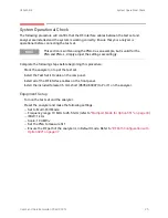
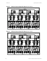
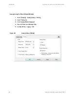
The 3.5 mm short will be relocated to each Test Port and an uncorrected reflection response
trace should be displayed that resembles the following plots indicated in
. If you
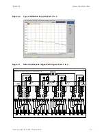
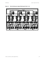
suspect an RF signal path problem, refer to the RF cable diagram and check the interface
cables associated with this signal path for proper installation.
The trace ripple (peak-peak variation) is normal for this raw uncorrected
measurement.
Table 10
Reflection Response Results
Reflection Port
Response Trace
Cable Path Diagram
Port 1 to 4
Ports 5 to 8
Ports 9 to 12
Ports 13 to 16
Ports 17 to 20
26
User's and Service Guide U3042-90012


