M9484C Startup Guide
77
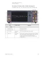
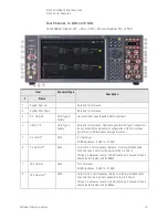
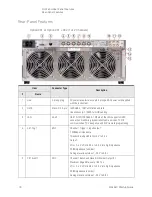
Front and Rear Panel Features
Rear-Panel Features
6
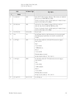
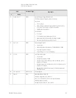
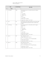
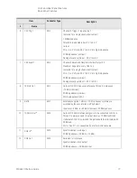
Ch2 Trig 1
BNC
Channel 2 Trigger 1 input/output:
(not used for a single channel instrument)
1 MΩ impedance
Threshold is adjustable from 0 V to 3.3 V
Output:
VOL < 0.4 V, VOH is 2.8 V to 3.3 V into high impedance
50 Ω impedance (nominal)
Damage level is outside of -0.5 V to 3.8 V
7
Ch2 Event 1
BNC
Channel 2 Baseband Waveform Marker Output #2
Maximum Edge Rate: every 1.667 ns
(not used for a single channel instrument)
VOL < 0.4 V, VOH is 2.8 V to 3.3 V into high impedance
50
Ω
impedance (nominal)
Damage level is outside of -0.5 V to 3.8 V
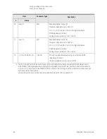
8
10 MHz Out
BNC
Output of 10 MHz frequency reference, this port is always on
+15 dBm (nominal)
50
Ω
impedance (nominal)
ESD damage level is 30 V
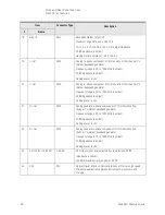
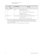
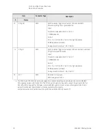
9
Ref In
BNC
Externally supplied 1 MHz to 110 MHz frequency reference,
switched by the user interface; off by default.
Input level -3 dBm to +20 dBm (nominal), 50
Ω
impedance.
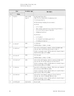
10
100 MHz Out
SMA
Output of 100 MHz reference signal is to be connected to SClk In.
This port is always on and its output level is +15 dBm (nominal).
If alternate SCLK In is provided this port should be terminated with
50 Ω load.
Ports 10 and 11 are connected by a factory installed cable.
11
SClk In
a
SMA
Synchronization clock input.
50
Ω
impedance. +2 dBm to +12 dBm
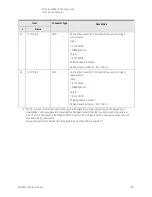
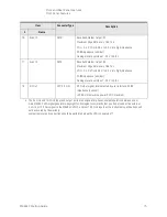
12
SClk Out
SMA
Reserved for future use.
Synchronization clock output.
50
Ω
impedance. +2 dBm nominal
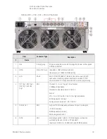
Item
Connector Type
Description
#
Name
Summary of Contents for M9484C
Page 4: ...4 ...
Page 8: ...8 M9484C Startup Guide ...
Page 20: ...20 M9484C Startup Guide Quick Start Verify Operation of the Signal Generator ...
Page 120: ...120 M9484C Startup Guide Using Windows Tools Windows Shortcuts and Miscellaneous Tasks ...
Page 128: ...128 M9484C Startup Guide Removable Solid State Drive SSD Instrument Security Information ...

