


42
M9484C Startup Guide
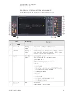
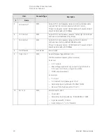
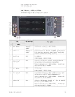
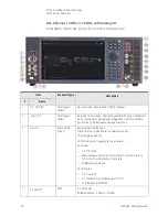
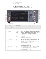
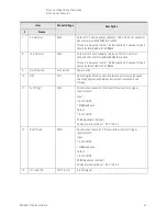
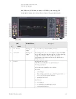
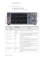
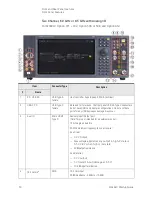
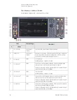
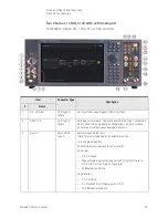
Front and Rear Panel Features
Front Panel Features
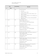
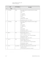
14
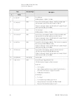
Event 2
BNC
Baseband Marker Output #2
Maximum Edge Rate: every 1.667 ns
VOL < 0.4 V, VOH is 2.8 V to 3.3 V into high impedance
50 Ω impedance (nominal)
Damage level is outside of -0.5 V to 3.8 V
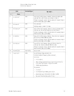
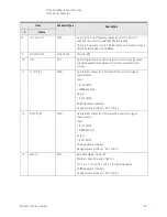
15
Event 3
BNC
Baseband Marker Output #3
Maximum Edge Rate: every 1.667 ns
VOL < 0.4 V, VOH is 2.8 V to 3.3 V into high impedance
50 Ω impedance (nominal)
Damage level is outside of -0.5 V to 3.8 V
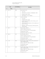
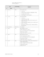
16
RF Out
1.85 mm
RF Output signal, level selected by user interface. 50 Ω
impedance (nominal)
+24 dBm maximum reverse power, 0 VDC Max
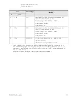
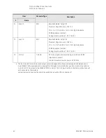
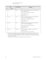
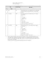
a. The 2.4 GHz and 19.2 GHz input and output ports are designed for phase coherent operation between one or
more M9484C VXG signal generators. Keysight Technologies recommends that you do not connect an external
2.4 GHz or 19.2 GHz signal to the M9484C VXG 2.4 GHz or 19.2 GHz inputs as the instrument specifications will
not be covered by the warranty.
Jumper removal and connection should be performed when the VXG is powered off.
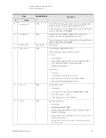
Item
Connector Type
Description
#
Name
Summary of Contents for M9484C
Page 4: ...4 ...
Page 8: ...8 M9484C Startup Guide ...
Page 20: ...20 M9484C Startup Guide Quick Start Verify Operation of the Signal Generator ...
Page 120: ...120 M9484C Startup Guide Using Windows Tools Windows Shortcuts and Miscellaneous Tasks ...
Page 128: ...128 M9484C Startup Guide Removable Solid State Drive SSD Instrument Security Information ...