30
M9484C Startup Guide
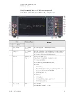
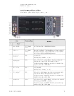
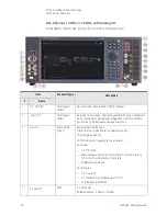
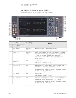
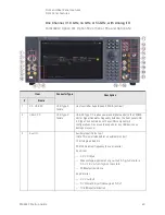
Front and Rear Panel Features
Front Panel Features
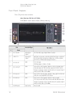
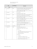
5
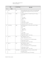
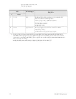
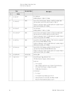
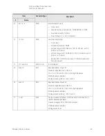
19.2 GHz Out
SMA
Output of 19.2 GHz frequency reference. A factory installed cable
connects the 19.2 GHz Out connector to the 19.2 GHz In.
This port is always on level is 7.3 dBm (nominal), if unused, this port
should be terminated with 50 Ω load.
6
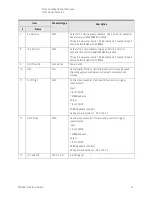
19.2 GHz Out
SMA
Output of 19.2 GHz frequency reference. The top right 19.2 GHz Out
connector is switchable and off by default.
7
19.2 GHz Out
SMA
Output of 19.2 GHz frequency reference. This 19.2 GHz Out
connector has a factory installed 50 Ω termination.
This port is always on level is 7.3 dBm (nominal), if unused, this port
should be terminated with 50 Ω load.
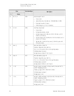
8
On/Off Switch
Push Button
Power Switch
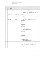
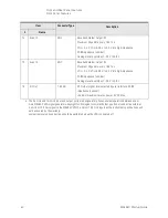
9
Trig A, B, or C
SMB
General Purpose Trigger/Marker Ports
100 MHz maximum frequency (drive or receive)
As a driver:
— 3.3 V output
— Max voltage applied at any output in high-Z state is
5.5 V and 3.8 V when in high or low state
— 50
Ω
output resistance
As a receiver:
— 5 V input
— 5 V tolerant input (damage at 5.5 V)
— Selectable input termination (50
Ω or 10 K Ω)
— Receiver threshold resolution (5 mV)
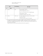
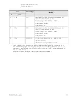
10
Ext 1 or 2
SMB
External Inputs 1 and 2
— 16 bit ADC
— Selectable input impedance: 50
Ω, 600 Ω, or 1 M Ω
— Input Bandwidth: 10 MHz
— Input Range: ±1 V (±5 V tolerant)
Item
Connector Type
Description
#
Name
Summary of Contents for M9484C
Page 4: ...4 ...
Page 8: ...8 M9484C Startup Guide ...
Page 20: ...20 M9484C Startup Guide Quick Start Verify Operation of the Signal Generator ...
Page 120: ...120 M9484C Startup Guide Using Windows Tools Windows Shortcuts and Miscellaneous Tasks ...
Page 128: ...128 M9484C Startup Guide Removable Solid State Drive SSD Instrument Security Information ...

