68
M9484C Startup Guide
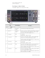
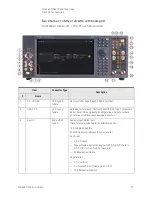
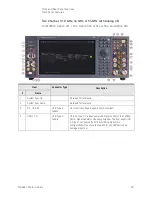
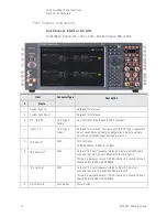
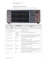
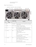
Front and Rear Panel Features
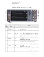
Front Panel Features
18
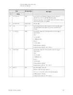
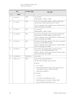
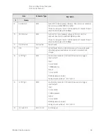
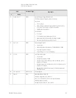
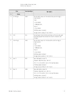
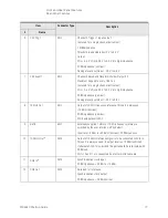
Event 3
BNC
Baseband Marker Output #3
Maximum Edge Rate: every 1.667 ns
VOL < 0.4 V, VOH is 2.8 V to 3.3 V into high impedance
50
Ω
impedance (nominal)
Damage level is outside of -0.5 V to 3.8 V
19
I+ Out
SMA
Analog In-phase component of I/Q modulation from channel 1's
internal baseband generator.
Frequency range is DC to 1000 MHz (nominal)
50
Ω
impedance (nominal)
Damage Level is ±2 V
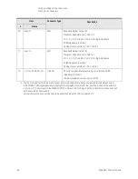
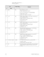
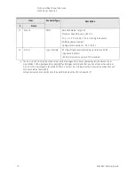
20
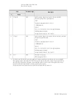
I
-
Out
SMA
Analog in-phase component of I/Q modulation from channel 1's
internal baseband generator.
Frequency range is DC to 1000 MHz (nominal)
50
Ω
impedance (nominal)
Damage Level is ±2 V
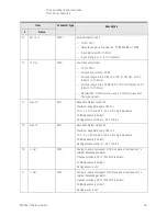
21
Q+ Out
SMA
Analog quadrature-phase component of I/Q modulation from
channel 1's internal baseband generator.
Frequency range is DC to 1000 MHz (nominal)
50
Ω
impedance (nominal)
Damage Level is ±2 V
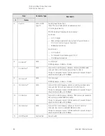
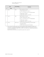
22
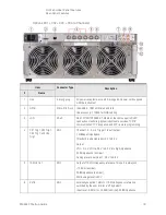
Q
-
Out
SMA
Analog quadrature-phase component of I/Q modulation from
channel 1's internal baseband generator.
Frequency range is DC to 1000 MHz (nominal)
50
Ω
impedance (nominal)
Damage Level is ±2 V
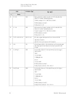
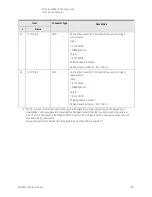
23
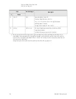
CH 1 and CH 2 RF Out
1.85 mm
RF Output signal, level selected by user interface. 50 Ω
impedance (nominal)
+24 dBm maximum reverse power, 0 VDC
24
ODI
ODI
Optical Digital Interface. Optical interconnect for very high speed
streaming applications between instruments, processors, and
storage.
Item
Connector Type
Description
#
Name
Summary of Contents for M9484C
Page 4: ...4 ...
Page 8: ...8 M9484C Startup Guide ...
Page 20: ...20 M9484C Startup Guide Quick Start Verify Operation of the Signal Generator ...
Page 120: ...120 M9484C Startup Guide Using Windows Tools Windows Shortcuts and Miscellaneous Tasks ...
Page 128: ...128 M9484C Startup Guide Removable Solid State Drive SSD Instrument Security Information ...

