1-18 (No.RA020<Rev.002>)
2.4
CIRCUIT DESCRIPTION
2.4.1 Overview
The NX-5700 is a VHF Analog FM & Digital Mobile transceiver designed to operate in the frequency range of 136 to 174MHz. The unit
consists of a receiver, a transmitter, a phase-locked loop (PLL) frequency synthesizer, a digital control unit, and a power supply circuit.
2.4.2 Frequency Configuration
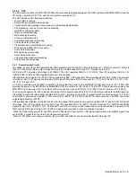
The receiver is a double-conversion super-heterodyne using first intermediate frequency (IF) of 49.95MHz and second IF of 2.25MHz.
Incoming signals from the antenna are mixed with the local signal from the VCO/PLL circuit to produce the first IF of 49.95MHz. This
is then mixed with the 47.7MHz second local oscillator output to produce the 2.25MHz second IF. The transmit signal frequency is
generated by the TX VCO, and modulated by the signal from the DSP. It is then amplified and fed to the antenna.
Fig.1 Frequency configuration
2.4.3 Receiver System
2.4.3.1
RF circuit
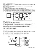
The receive signal from antenna switch (D310, D311, D312, D313, D314 and D315) is amplified by a RF amplifier (Q502) and passes
through the band-pass filter (L517, L516, L514, L511, L509 and L508) to remove unwanted signals. The signal is then fed to the 1st
mixer (IC500).
2.4.3.2
IF circuit
The first IF signal is passed through a four-pole monolithic crystal filter (XF600) to reject adjacent channel signal. The filtered first IF
signal is amplified by the first IF amplifier (Q604 and Q603) and then applied to the IF system IC (IC600). The IF system IC provides
a second mixer, second PLL, AGC and A/D converter.
The second mixer mixes the first IF signal with the 47.7MHz of second local oscillator output and produces the second IF signal of
2.25MHz.
The second IF signal is then be fed into an A/D converter, generates the I and Q data. This data is in the form of SSI (Serial Synchro-
nous Interface), and sent to the DSP (IC706).
2.4.3.3
Audio amplifier circuit
Audio processing (high-pass filter, low-pass filter, de-emphasized and so on) at Analog FM mode and decoding at Digital mode are
processed by DSP. SSI signal from DSP is converted to audio signal at IC902. The signal goes to internal speaker and connector for
external speaker (J900) through the amplifier (IC903), electronic volume control (IC719) and audio amplifier (IC911).
Fig.2 RF and IF circuit
ANT
1st MIX
49.95MHz
47.7MHz
SP
19.2MHz
185.95~223.95MHz
MIC
136~174MHz
ANT
SW
PA
AMP
RF
AMP
TX
AMP
MCF
MIX
IF Circuit
TCXO
RX
VCO
2nd
VCO
PLL
TX
VCO
Baseband
Circuit
CODEC
AF
AMP
TX/RX: 136~174MHz
ANT
D310,311
Q600
D312,313
L516
Q502
L508,509
D314,315
L517
RF AMP
L514,511
IC500
XF600
Q604
Q603
SSI
MCF
IF AMP
IF AMP
IC600
RX VCO/PLL
Internal Speaker
IC706
IC902
IC903
IC719
IC911
External Speaker
J900
ANT
LPF
ANT
SW
BPF
BPF
BPF
IF IC
2nd
VCO
DSP
CODEC
VOL
Summary of Contents for NX-5700
Page 106: ...MEMO ...
Page 137: ...MEMO ...

