DV-5050M/5900M/DVF-J6050/J6050-G
9
CIRCUIT DESCRIPTION
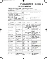
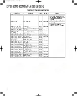
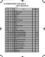
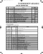
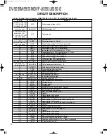
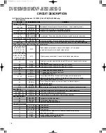
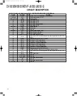
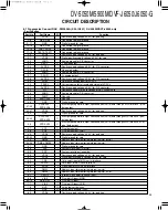
Port No.
Port Name
I/O
Function
Active
H
L
61
AVSS
-
Connected to GND.
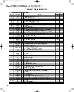
62
LED DVD
O
DVD active led control port.
63
LINE3
-
Unused.
64
AVREF1
-
Connected to VDD.
65
SI0
I
Data input from DVD microcomputer.
66
SO0
O
Data output to DVD microcomputer.
67
SCK0
I
Clock input from DVD microcomputer.
68
SI1
I
Data input from sub microcomputer.
69
SO1
O
Data output to sub microcomputer.
70
SCK1
I/O
Clock input/output between main/sub microcomputer.
71
STB SUB
O
Strobe signal output to sub microcomputer.
72
STB
O
Strobe signal output to display microcomputer (X14, IC).
73
SI
I
Data input from display microcomputer (X14, IC).
74
SO
O
Data output to display microcomputer (X14, IC).
75
SCK0
O
Clock output to display microcomputer (X14, IC).
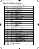
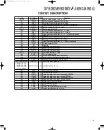
76~83
A0~A7
O
Address bus of SRAM (X25, IC14).
84~91
AD0~AD7
I/O
Data bus of SRAM (X25, IC14).
92~99
A8~A15
O
Address bus of SRAM (X25, IC14).
100
VSS
-
Connected to GND.
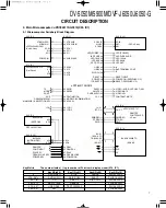
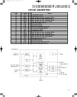
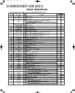
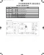
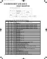
X25, IC1
Main Microcomputer
uPD784217AGF519
SCX0 99
S.DT
98
M.DT
97
S.RQ 95
M.RQ 96
DVM-01
STCKER MOTOR +
56 R CCW
STCKER MOTOR -
55 R CW
DOOR MOTOR +
51 DOOR CLOSE
DOOR MOTOR -
52 DOOR OPEN
CLUMP MOTOR +
53 CLUMP -
CLUMP MOTOR -
54 CLUMP +
LOADING MOTOR +
57 UNLOAD
X25, IC13
LOADING MOTOR -
60 LOAD
D 1
91 PWM
IERX 26
Daisy Chain
Q 1
68 D SW
Drive IC
PH 1
70 PH 1
IETX 27
HA12187FP
PH 3
71 PH 3
Sub
PH 2
72 PH 2
Microcomputer
S1
77 LOCK SW
X25, IC12
S2
78 CLOSE SW
D2
89 EJECT LED
DSR 4
DSR
S3
61 OPEN SW
DTR 5
DTR
S4
63 EJECT SW
RXD 1 6
TD
S5
64 0 SW
TXD 1 7
RD
S6
66 180 SW
MAX232NS
S7
67 90 SW
PC Drive IC
S9
79 PL SW
S8
80 HP SW
S LED
92 S LED
4 DSR
5 DR
T
6 RXD1
7 TXD1
X25(IC12)
DSR
DTR
TD
RD
PC Drive IC
MAX232NS
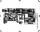
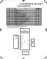
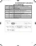
5. Sub Microcomputer: 703034AGFA01(X25-644/655, IC2)
5-1 Sub Microcomputer Periphery Block Diagram
www. xiaoyu163. com
QQ 376315150
9
9
2
8
9
4
2
9
8
TEL 13942296513
9
9
2
8
9
4
2
9
8
0
5
1
5
1
3
6
7
3
Q
Q
TEL 13942296513 QQ 376315150 892498299
TEL 13942296513 QQ 376315150 892498299


