background image

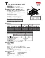
Model KP0810 features the following user-friendly advantages:
*Left and right chip ejection for convenience
*Precise planing depth setting by adjustment dial with click stops
  and easy-to-read scale with 0.1mm divisions
*Front base with 3 chamfering grooves
*Shiplapping Cuts: up to 25mm (1")

Model KP0810C additionally features the followings:
*Electronic with soft start and constant speed control
*Powerful 1,050 W motor

Models No.

 Description

PRODUCT

T

ECHNICAL INFORMATION

C

ONCEPT AND MAIN APPLICATIONS


S

pecification

S

tandard equipment

O

ptional accessories

Note: The standard equipment for the tool shown above may differ by country.

P 1 /11

KP0810, KP0810C

Power Planer 82mm (3-1/4")

Dimensions: mm (")

These products are available in the following variations.

Width (W)

Height (H)

Length (L)

290 (11-3/8) 

168 (6-5/8) 

176 (6-15/16) 

L

W

H

KP0810/ KP0810C

without Plastic carrying case

KP0810K/ KP0810CK

with Plastic carrying case

Continuous Rating (W)

Voltage (V)

Cycle (Hz)

Input

Output

Max. Output (W)

110
120

220
230
240

8.1
7.5

4.1
3.9
3.7

11
10

6
6
6

50/60
50/60

50/60
50/60
50/60

850

---

850
850
850

1,050

---

1,050
1,050
1,050

500
500

500
500
500

900
900

900
900
900

1,200
1,200

1,700
1,700
1,700

Current (A)

KP0810

KP0810

KP0810C

KP0810C

KP0810

KP0810C

Blade gauge assembly
Depth guide
Guide rule
Socket wrench 9
Planer blade (re-sharpenable type) or T.C.T. Mini planer blade
Sharpening holder assembly (for countries using re-sharpenable type Planer blade)
Dust bag (UK only)
Plastic carrying case (for KP0810K/KP0810CK)

Guide rule
Chamfering rule assembly
Dust bag
Sharpening holder assembly
Blade gauge assembly

Planer blade (re-sharpenable type)
T.C.T. Mini planer blade
Dressing stone
Elbow
Plastic carrying case

*2.0m (6.6ft) for Australia, 4.0m (13.1ft) for Germany

82 (3-1/4)

4 (5/32)

25 (1)

3.2 (7.2)

3.3 (7.3)

*2.5 (8.2)

16,000

12,000

Double insulation

KP0810

KP0810C

No load speed: min

-1

=rpm

Model No.

Planing width
Planing depth
Shiplapping

Net weight: kg (lbs)

Electronic
features

Protection against electric shock

Power supply cord: m (ft)

Constant speed control

No

Soft start

No

Yes

Yes

Capacities: mm (")

Summary of Contents for KP0810

Page 1: ...oltage V Cycle Hz Input Output Max Output W 110 120 220 230 240 8 1 7 5 4 1 3 9 3 7 11 10 6 6 6 50 60 50 60 50 60 50 60 50 60 850 850 850 850 1 050 1 050 1 050 1 050 500 500 500 500 500 900 900 900 90...

Page 2: ...ring 3 Cam Tapping screw bind CT 4x12 5 67 69 Leaf spring 2 pcs Steel ball 4 2 pcs Front base complete Surface that contacts Housing Whole surface Hole for accepting Cam Edges on which Housing slides...

Page 3: ...ulley 4 37 Fig 3 1R350 1R350 Front base Base Fig 2 Fig 4 Hold the machine securely by putting Base and Front base on the shaded portion of 1R350 Belt cover Poly V belt 4 241 V Pulley 4 20L Assemble Po...

Page 4: ...Then disconnect Carbon brushes from Commutator of Armature 3 Put the machine on two 1R350 s with Bracket complete side up refer to Fig 2 Unscrew four 4x18 Tapping screws that fasten bracket complete...

Page 5: ...ng 6200DW remains assembled to Drum holder section to be disassembled in step 4 to 8 5 By removing two 5x25 Tapping screws from the Rear cover side of Housing Drum holder section can be disassembled a...

Page 6: ...of Housing as illustrated in Fig 20 3 Do the reverse of the disassembling steps 4 to 1 Figs 14 to 12 Drum cover Torsion spring 10 Tapping screw 5x25 Tapping screw 5x25 Drum holder complete pin of Dru...

Page 7: ...page 2 2 Insert Cam through the hole of Housing from the bottom side of Housing as illustrated in Fig 25 3 Assemble Front base to Cam then provisionally install Front panel on Housing Fig 26 4 Adjust...

Page 8: ...ete side Fig 28 2 Fasten four 4x18 Tapping screws while making sure that the ruler is exactly square against Front base and Base Fig 28 Drum holder complete Ruler Front base Base Fig 28 3 6 Planer Bla...

Page 9: ...andle R from Handle L by unscrewing five 4x18 Tapping screws as illustrated to left in Fig 31 Now the electrical parts illustrated to right in Fig 31 can be removed from Housing L Note If it is diffic...

Page 10: ...Carbon brush Carbon brush Pickup coil Power supply cord White Lead wire is used for some countries Controller Black White Red Blue Color index of lead wires sheath Black White Color index of lead wir...

Page 11: ...these portions of Housing If Noise suppressor is used put in this portion If Noise suppressor is used put in this portion Noise suppressor if used Route Field lead wires through these portions of Hous...

Reviews: