


P 4 /11
[3] DISASSEMBLY/ASSEMBLY
[3] -2. Motor Section
R
epair
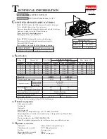
1R263
Bracket complete
Bracket complete
Armature
Baffle plate
Duct assembly
with Nozzle
Drum complete
1R263
Fig. 9
Fig. 10
Fig. 11
Wrench 13
V-Pulley 4-20L
Do the reverse of the disassembling steps.
Note: Do not forget to assemble Baffle plate, duct assembly and Nozzle to Housing. (Fig. 9)
Tapping screw 4x18
(2 pcs)
Tapping screw 4x18
(4 pcs)
Rear cover
1) Remove Poly V-belt 4-241 as illustrated in Fig. 2 to Fig. 4.
Note: Armature cannot be removed from Bracket complete until the Poly V-belt is removed from Pulleys.
2) Remove Rear cover by unscrewing two 4x18 Tapping screws. (Fig. 7)
Then disconnect Carbon brushes from Commutator of Armature.
3) Put the machine on two 1R350's with Bracket complete side up. (refer to Fig. 2.)
Unscrew four 4x18 Tapping screws that fasten bracket complete to Housing. (Fig. 8)
4) Remove Bracket complete together with Armature and Drum complete by levering off Bracket compete from Housing
using two 1R263's. Duct assembly can be removed together with Nozzle. (Fig. 9)
5) Remove V-Pulley 4-20L from Armature shaft by turning clockwise with Wrench 13. (Fig. 10)
Important: Wear gloves to prevent injury to be caused by the sharp edge of Drum complete.
6) Armature can now be removed from Bracket complete by tapping Bracket complete with plastic hammer
as illustrated in Fig. 11.
Fig. 7
Fig. 8
DISASSEMBLING
1R350
Bracket complete
Housing
Armature
Drum complete
Armature
Bracket complete
ASSEMBLING


