MY-A Series (10kVA-20kVA) UPS
User Manual
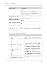
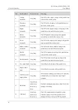
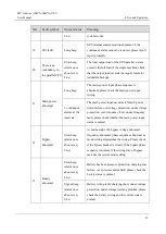
5 LCD Screen Operation
79
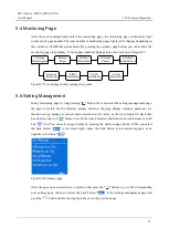
5.4 Monitoring Page
After the system automatically enters the monitoring page, the monitoring page in the lower right
corner shows page number. The total number of monitoring pages displayed is changes depending on
the current set of different system mode. By pressing the up/down page button, you can achieve the
monitoring page loop display. 33 mode page number and page loop order as shown in Figure5-7.
1.Energy
Flow Diagram
9.Device
Information
8.BAT
Information
7.BYP
Information
6.Grid
Information
5.Output
Load Percent
4.Output
Power
3.Output
Information
2.Detail
Page
Figure5-7
33 mode page number and page loop order
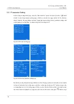
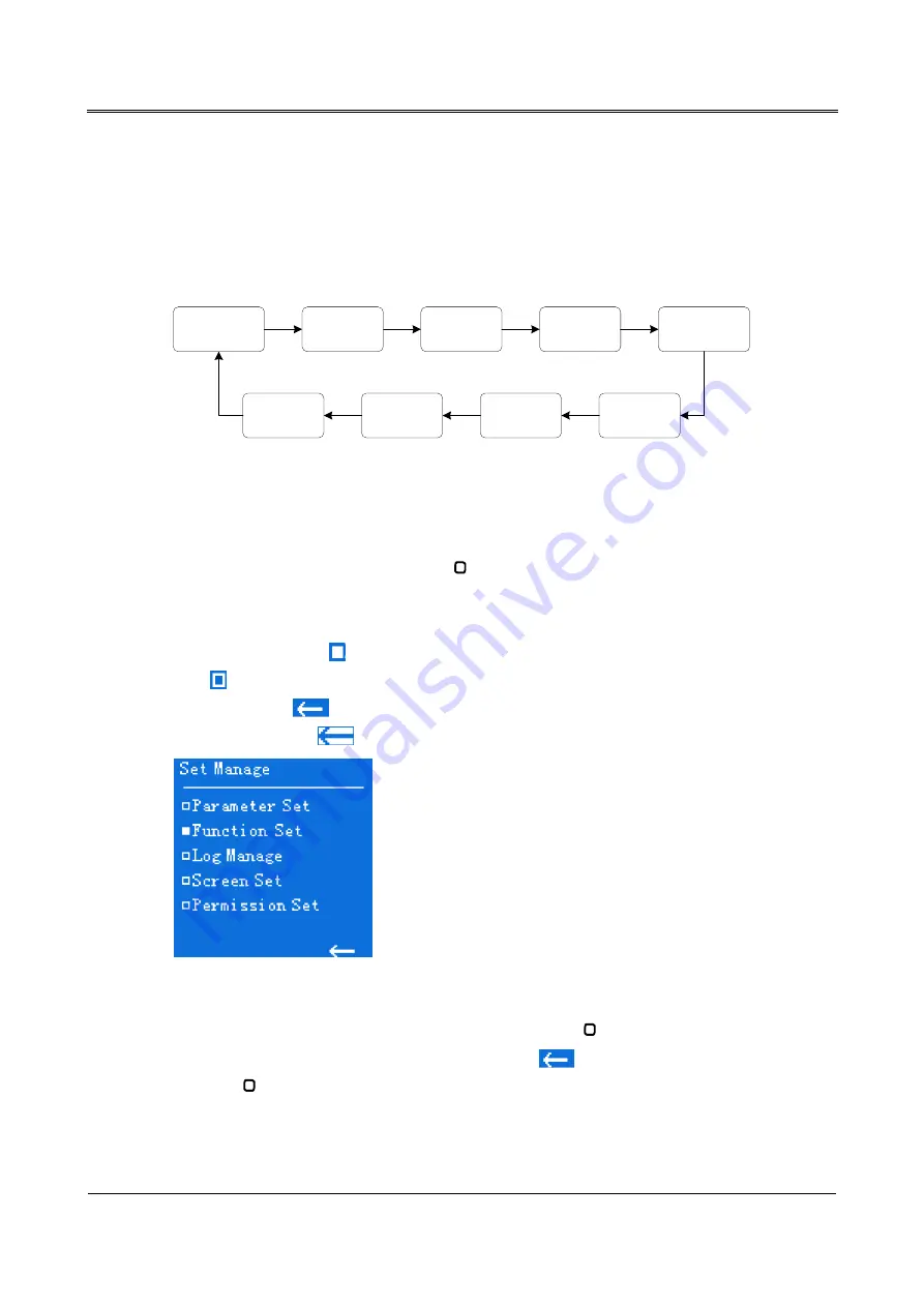
5.5 Setting Management
In any monitoring page by long pressing "
"
button for 3s can enter the settings management page,
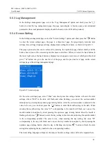
the page is mainly for the directory display function, the page display includes: parameter set,
function set, log manage, screen set and permission set five items, as shown in Figure5-8. Each item
has a hollow box icon "
" before it, and if the item is selected, the hollow box icon becomes a solid
box "
" icon. You can select page content by pressing the up/down page button. When you select
the back button "
" to the lower right corner, the back button is selected and appears as an
opposite color status "
".
Figure5-8
Set manage page
After the page option selection is complete, short press the "
"
button to go to the corresponding
next settings page. When you select the back button "
" in the settings management page and
press the "
"
button shortly, the display takes you to the previous page.


