Keba KeDrive D3-DA BG3 Operation Manual Download Page 55

55

1  Commissioning

Operation Manual KeDrive D3-DA BG3 and BG4 

1804.200B.1-01    Date: 03/2023

Commissioning

2. 

Switch off system.

3. 

The next time after switching on up to three yellow LEDs on the first axis controller illuminate 
briefly, depending on the number of axes, and are then illuminated continuously for approx. 
4 seconds after approx. 14 seconds. This process is repeated during each switch-on process. 
Only exception: after a firmware update, the upstream supply unit may also be updated during 
the restart in certain circumstances. As a consequence, the start process may be delayed once 
by approx. 2 minutes. The loading of the firmware for the supply unit is indicated by the flashing 
(0.5 s/0.5 s) of the two LED on the supply unit.

4. 

If the connector for the EtherCAT and the cross-communication on the input on the first axis 
controller in the axis block (first axis controller - X40A XCIN) is disconnected within 4 seconds 
and connected again, the interface is placed in the service and diagnostics mode the next time it 
is switched on.  
The activation of the interface switchover is indicated by fast flashing (0.1 s/0.1 s) on all axis 
controllers connected via the cross-communication.

5. 

Switch system off and on again.  
All axis controllers operate in the service and diagnostics mode (standard Ethernet). This situation 
is indicated by slow flashing of the yellow LEDs (0.8 s/0.8 s). 
IP, subnet mask and gateway are only configured in the first axis controller and are incremented 
or applied in downstream devices also connected via cross-communication.

6. 

The devices also remain in this mode after a restart. Only if the service and diagnostics mode 
is terminated as described in the section "Exiting service/diagnostics mode" is the EtherCAT 
operation mode again always active.

NOTE:

Interface switchover and the activation of new IP configuration settings are 
only active after a restart. As soon as an axis controller in the group has 
detected a change to the current configuration, the fast flashing (0.1


s/ 0.1


s) 

yellow LED indicates that a restart is required; this statement also applies to 
the termination of the service and diagnostics mode (see also section "Exiting 
service/diagnostics mode"). 
A stable operating state is only achieved once none of the yellow LEDs in the 
axis group is flashing quickly (0.1


s/0.1


s)!

1

3

4

2

8

6

7

5

CC-Master 1

CC-Master 2

X40A

X40B

X40A

X40B

X40A

X40B

X40A

X40B

X40A

X40B

X40A

X40B

X40A

X40B

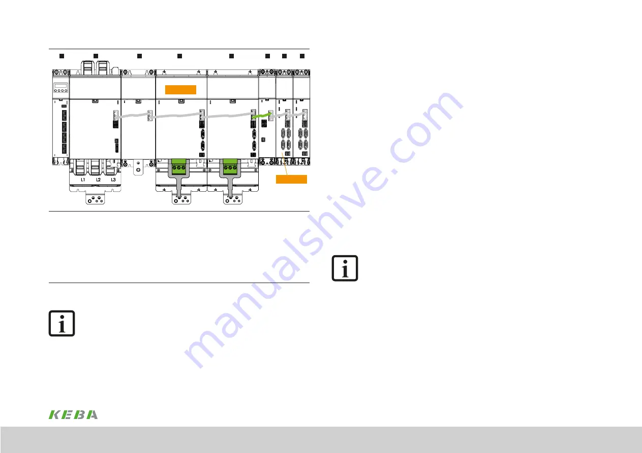
Expanded axis group with supply unit, capacitance module and axis controllers of sizes BG3 and BG4 and axis 

controllers of sizes BG1 and BG2 attached via expansion module --> two cross-communication groups

Cross-communication group 1:

Axis group with one supply unit and a maximum of 8 additional bus users

Cross-communication group 2

:

Expansion module and a maximum of 8 additional bus users
1: Controller | 

2: Supply unit | 

3: Capacitance module | 

4: Axis controller (CC-Master 1)  

5: Axis controller |  6: Expansion module |  7: Axis controller (CC-Master 2) |  8: Axis controller

Figure 5.3  Cross-Communication (CC) in two groups

NOTE:

The cross-communication is via the 8-core Ethernet cables that are included 
with the modules. The cross-communication can be separated using a 4-core 
Ethernet cable - shown here with the green connection. The 4-core cable can 
be ordered in different lengths. The order designation is XW 021-xxx where 
xxx specifies the length of the cabled (xxx * 10 cm). 
Two axis groups (two separate cross-communication groups) are shown in 
this figure. 

Summary of Contents for KeDrive D3-DA BG3

Page 1: ...Operation manual Compact multi axis system KeDrive D3 KeDrive D3 DA Axis Controller BG3 and BG4...

Page 2: ...300 A rated current With the aid of the KeDrive D3 DE expansion module the KeDrive D3 DA axis controllers BG1 and BG2 can be combined with the KeDrive D3 DA axis controllers BG3 and BG4 without proble...

Page 3: ...ection according to DIN EN 61800 5 1 35 4 4 2 Connection principle 36 4 5 Electrical isolation concept 36 4 6 Connection of the supply voltages 37 4 6 1 24 V control supply 38 4 6 2 Power supply 38 4...

Page 4: ...nection 41 4 8 1 Motor connection diagram 42 4 8 2 Motor holding brake monitoring output 45 4 8 3 Specification for motor connections 45 4 8 4 Switching in the motor cable 46 4 8 5 Electronic overload...

Page 5: ...and understand the documentation on the device y Qualification to prevent injury or damage personnel may only work on the device if they have electrical engineering qualifications y Knowledge require...

Page 6: ...Output frequency limiting 600 Hz with protective coating Version 0 First version 1 New field bus controller2 1 second figure applies to liquid cooled variant 2 preferred option 3 hardware version 0 on...

Page 7: ...pansion module D3 DE Single model D3 DE Single Dual model D3 DE Dual Dual End model D3 DE Dual End Size BG 1 and size BG 2 BG1 and BG2 Size BG 3 and size BG 4 BG3 and BG4 NOTE The axis controllers KeD...

Page 8: ...ulations If necessary dispose of individual parts depending on their characteristics and existing national regulations e g as y Electrical waste y Plastic y Metal Or engage a certified disposal organi...

Page 9: ...nel on the device Rotating parts Automatically starting drives Hot components and surfaces 3 Protection against magnetic and or electromagnetic fields during installation and operation Persons fitted...

Page 10: ...s document Pay attention to special safety instructions and warnings that are given here in the document before a specific action and that warn the user about a specific hazard NOTE The pictograms may...

Page 11: ...rs with speed position feedback y Supply with DC voltage y Supply with single phase AC voltage y Supply with low voltage 100 V 2 5 Misuse Our devices are y Not intended for installation in vehicles De...

Page 12: ...UKCA UKCA UKCA UK Conformity Assessed is the British product marking required for certain products placed on the market in Great Britain England Wales and Scotland Authorised representative is KEBA Lt...

Page 13: ...EC Machinery Supply of Machinery Safety Regulations 2008 2014 30 EU Electromagnetic Compatibility Electromagnetic Compatibility Regulations 2016 2011 65 EU Restriction of Hazardous Substances in Elect...

Page 14: ...14 1 Safety Operation Manual KeDrive D3 DA BG3 and BG4 1804 200B 1 01 Date 03 2023 Safety...

Page 15: ...elines apply to the arrangement and installation of the axis controller or supply unit Butt mounting and alignment y The devices can be mounted directly beside each other without any spacing They are...

Page 16: ...distance from neighbouring assemblies particularly above the heat sink 3 2 Mounting clearances CAUTION Damage to the device due to incorrect installation conditions The device may suffer irreparable d...

Page 17: ...e mounting clearances may increase significantly due to the bending radii necessary 3 3 Cooling of the devices with air cooling Cooling air must be able to flow through the device interior and heat si...

Page 18: ...n the backing plate Drill holes in the backing plate and cut a thread for each fixing screw in the backing plate Pay attention to the bending radius of the connection cables For hole spacing and dimen...

Page 19: ...1 Mounting holes A 27 27 A1 110 220 C 4 8 4 8 D 80 80 E 98 H1 378 378 H2 6 6 H3 390 390 Screws 4 x M4 4 x M4 All dimensions in mm 1 Without terminals and connectors Table 3 1 Table of dimensions KeDri...

Page 20: ...in the scope of supply into the pipe fittings lock the pipe fittings using a 22 mm open ended wrench to prevent damage due to the application of torque to the device The contact surface must be bare...

Page 21: ...H E G F G 3 8 15 tief T T1 A2 D1 25 Figure 3 8 Dimensional drawing D3 DA 3xx axis controller BG4 example 1x 250 A B H1 A C A1 H2 H3 D H E G F G 3 8 15 tief T T1 A2 D1 25 Figure 3 9 Dimensional drawin...

Page 22: ...g is connected to the connection correspondingly marked in Figure 3 9 1 2 R cklauf return Vorlauf flow 3 4 5 2 flow return 1 Liquid connection with 3 8 inch female thread 2 90 elbow fitting with 3 8 i...

Page 23: ...controller BG3 8 bus users with 11 axes Figure 3 11 KeDrive D3 DA BG3 all components Note 1 controller 1 supply unit 1 capacitance module 1 single axis controller BG4 3 double axis controllers BG3 and...

Page 24: ...24 1 Operation Manual KeDrive D3 DA BG3 and BG4 1804 200B 1 01 Date 03 2023...

Page 25: ...ng up intended operation is only permitted while strictly complying with the EMC Directive 2014 30 EU The installer organisation operating a machine and or system must provide proof of compliance with...

Page 26: ...tors relays solenoid valves switched inductances must be wired with suppressors The wiring must be directly connected to the respective coil y Any switched inductance should be at least 0 2 m away fro...

Page 27: ...IN input field bus See Chapter 4 10 X40B EtherCAT OUT output field bus X25A Digital inputs programmable See Chapter 4 7 1 X48A X48C Encoder interface See Chapter 4 9 1 X48B X48D Encoder interface X26A...

Page 28: ...DA BG4 up to 250 A single axis controller X31A X31A U V W PE Status Axis 1 DC Link 24 V DC X40A X40B X25A X48A X48B X26A Safety Figure 4 4 Layout KeDrive D3 DA BG4 300 A single axis controller 28 1 El...

Page 29: ...er 4 9 1 X48B Encoder interface X26A Digital inputs safety function See Chapter 4 7 2 S ADR DIL switch bank for the configuration of the SD0 functionality See Model description SD0 ID no 1404 252B x X...

Page 30: ...n Designation Details X40A EtherCAT IN input field bus Can also be used as Ethernet interface for PC with DriveManager For information about activating the service diagnostics mode see chapter 5 1 3 X...

Page 31: ...esolver excit 10 R1 resolver excit 10 R1 resolver excit 11 B SIN S2 SIN B 11 B S2 SIN B 12 Temp 1 12 Temp 1 13 Temp 1 13 Temp 1 14 CLK MA 14 15 CLK MA 15 Table 4 6 Pin assignment connector X48A Enc1 s...

Page 32: ...ervice diagnostics mode see chapter 5 1 3 X40B EtherCAT OUT output field bus X25A Digital control inputs X48A Encoder connection 1 axis 1 Enc1 multi encoder interface X48B Additional encoder connectio...

Page 33: ...xcit 9 R2 resolver excit 10 R1 resolver excit 10 R1 resolver excit 11 B SIN S2 SIN B 11 B S2 SIN B 12 Temp 1 12 Temp 1 13 Temp 1 13 Temp 1 14 CLK MA 14 15 CLK MA 15 Table 4 9 Pin assignment connector...

Page 34: ...xcit 9 R2 resolver excit 10 R1 resolver excit 10 R1 resolver excit 11 B SIN S2 SIN B 11 B S2 SIN B 12 Temp 1 12 Temp 1 13 Temp 1 13 Temp 1 14 CLK MA 14 15 CLK MA 15 Table 4 11 Pin assignment connector...

Page 35: ...lowing minimum re quirements for the protective earth conductor cross section as a function of the phase conductor cross section as per EN 61800 5 1 Cross section of the phase conductors Minimum cross...

Page 36: ...bbre viation Busbars 24 V DC Control section supply voltage Protective extra low voltage circuit 3 PELV Busbars ZK Supply voltage DC link Low voltage 1 ZK X40A X40B EtherCAT IN OUT field bus connectio...

Page 37: ...its 24 V supply from the supply unit via the upper busbars 24V DC and GND The power section in the axis controller receives its DC link supply from the supply unit via the lower busbars DC Link and DC...

Page 38: ...ply NOTE If an external 24 V supply is used it must provide safe isolation as per EN 61800 5 1 or EN 50178 4 6 2 Power supply The supply voltage for the axis controllers is supplied by the supply unit...

Page 39: ...DP 3xx Then connect X40B on the supply module to X40A the first axis controller The cables required are included in the scope of supply of the modules EtherCAT interface specification See Chapter 4 10...

Page 40: ...put Touch probe DI10 Fast dig input Touch probe GND DGND Reference ground Table 4 15 Allocation of the control inputs example double axis controller Des Term Specification Electrical isolation DI00 X2...

Page 41: ...tors X31A X31B It is intended to connect one motor X31A to the BG4 axis controller Step Action Comment 1 Specify the cable cross section depending on the maximum current and ambient temperature Select...

Page 42: ...temperature sensor must be designed with reinforced insulation according to EN 61800 5 1 CAUTION Damage to the system due to uncontrolled coasting down of the motor If there is a short circuit or eart...

Page 43: ...mmended connection of the motor holding brake from max 2 A motor brake current The temperature sensor connection is shown in the version with standard encoder interface Figure 4 13 Connection of two s...

Page 44: ...the encoder is connected to connector HDSL on the Hiperface DSL model see order code Note In preparation and only for KeDrive D3 DA BG3 up to 45 A Figure 4 15 Connection of two servomotors with Hiperf...

Page 45: ...V W on single axis controllers BG3 and to the connectors X31A U V W and X31B U V W on double axis controllers BG3 The terminals for the motor phases are fixed on the single axis controller BG4 The mo...

Page 46: ...apter 7 1 4 8 5 Electronic overload protection for the motor The motor protection function acquires the motor frequency the motor current and other parameters Depending on these parameters shown in th...

Page 47: ...ails about the possible combinations of motor encoder and corresponding cables in the order catalogue System Cables and in the related motor catalogues Document Contents ID no Format KeDrive D3 System...

Page 48: ...N1381 ROD486 Heidenhain SinCos encoder with EnDat interface e g 13 bit singleturn encoder ECN1313 EnDat01 and 25 bit multiturn encoder EQN1325 EnDat01 SinCos encoder with SSI interface e g 13 bit sing...

Page 49: ...y from pin 3 typ 5 25 V max 5 4 V NOTE The encoder supply on X48B and X48D is short circuit proof during both 5 V and 10 V operation The controller remains in operation enabling the generation of a co...

Page 50: ...Achse 2 Achse 3 tatusanzeige 1 X48C Axis2Enc1 xis2Enc2 X25A X48A Axis1Enc1 xis1Enc2 X25A X48A X48B X48C X48D OUT0 Output EtherCAT X40B LEDs Ethernet ports L A Green Port0 Link Activity RUN Green Devic...

Page 51: ...ly busbars 11 KeDrive D3 DP supply unit BG3 and BG4 12 KeDrive D3 DA axis controllers BG3 and BG4 13 Switch cabinet 14 Field 15 See Operation Manual KeDrive D3 DP Supply Unit 16 Backing plate 17 See O...

Page 52: ...52 1 Electrical installation Operation Manual KeDrive D3 DA BG3 and BG4 1804 200B 1 01 Date 03 2023 Electrical installation...

Page 53: ...modules have two connections for establishing an EtherCAT network X40A ECAT IN and X40B ECAT OUT Here connection X40A ECAT IN is the input and connection X40B ECAT OUT the output The output ECAT OUT r...

Page 54: ...is necessary to identify the first axis controller cross communication master on the right side of the power supply within the cross communication to activate the service and diagnostics mode Dependi...

Page 55: ...iagnostics mode is terminated as described in the section Exiting service diagnostics mode is the EtherCAT operation mode again always active NOTE Interface switchover and the activation of new IP con...

Page 56: ...ics mode double axis controller NOTE While the cross communication to the supply unit is interrupted power can not be applied to the axis controllers 5 1 4 Exiting the service diagnostics mode After t...

Page 57: ...er The interface switchover selected is again signalled by the yellow LEDs flashing quickly 0 1 s 0 1 s during the next power up The interface switchover selected is signalled by the yellow LEDs flash...

Page 58: ...any damage that occurs NOTE Details in relation to STO Safe Torque Off do not need to be taken into account for initial commissioning You will find all information about the STO function in the docum...

Page 59: ...ta sets can be loaded directly from KeStudio DriveManager The data sets for the motor range DMS2 are saved in the encoders and are loaded directly from there NOTE You will find a detailed description...

Page 60: ...u start commissioning it must be ensured that the machine will not be damaged by the test Pay particular attention to the limitations of the positioning range Certain motors are only intended for oper...

Page 61: ...rvice on the EtherCAT master Figure 5 9 Advanced EtherCAT master settings 5 4 Standard operation on the KeDrive D3 DU controller For standard operation a KeDrive D3 DU controller is connected to the X...

Page 62: ...unication with KeStudio DriveManager The virtual IP address configured in the previous step is to be used for the EoE communication Figure 5 11 Establishing communication with KeStudio DriveManager St...

Page 63: ...power stage active Figure 6 1 Status LEDs 6 1 1 Flashing code The Axis 1 2 LEDs yellow only have a defined function during a software update LED yellow LED red LED green Axis status Axis 1 2 long 0 8...

Page 64: ...the Error history button to retrieve information about the last 20 errors that have occurred Figure 6 3 Device status window If an error occurs a pop up window appears immediately with more detailed...

Page 65: ...ed information about all errors and warnings that have occurred 1 In the tree in the Project window click Alarms Warnings 2 In the new window that opens you will find the history for the errors and wa...

Page 66: ...66 1 Operation Manual KeDrive D3 DA BG3 and BG4 1804 200B 1 01 Date 03 2023...

Page 67: ...nputs on the axis controller s control board NOTE You will find all further information about the STO and SBC functions in the document Model Description SD0 ID no 1404 252B x 7 2 SDC model The SDC mo...

Page 68: ...68 1 Safety design variants Operation Manual KeDrive D3 DA BG3 and BG4 1804 200B 1 01 Date 03 2023 Safety design variants...

Page 69: ...urrent at the 24 V power supply unit per device A 1 8 A at 24 V 1 s and 2 2 A at 18 V 1 s Control voltage for motor holding brake with cable length 50 m V DC 22 8 24 V 5 Power consumption per encoder...

Page 70: ...2 97 02 164 90 220 00 291 33 Rated current 230 V 400 V 8 kHz A 16 10 21 50 30 20 30 20 53 70 65 00 120 00 Maximum current A 45 30 60 40 85 00 85 00 144 50 123 87 200 00 Duration of maximum current ms...

Page 71: ...Rated current 480 V 8 kHz A 15 20 20 30 28 50 28 50 50 70 54 00 110 00 Maximum current A 37 30 49 80 70 00 70 00 119 00 113 14 175 00 Duration of maximum current ms 500 00 500 00 500 00 500 00 500 00...

Page 72: ...0 Hz A 51 76 69 01 97 02 97 02 164 90 220 00 291 33 375 00 Rated current 230 V 400 V 8 kHz A 16 10 21 50 30 20 30 20 53 70 80 00 150 00 190 00 Maximum current A 45 30 60 40 85 00 85 00 144 50 123 87...

Page 73: ...1 141 14 185 35 244 66 255 00 Rated current 480 V 8 kHz A 15 20 20 30 28 50 28 50 50 70 65 00 130 00 165 00 Maximum current A 37 30 49 80 70 00 70 00 119 00 113 14 177 00 330 00 Duration of maximum cu...

Page 74: ...imum values for temperature and relative atmospheric humidity stipulated in the table must not occur simultaneously 3 The absolute humidity is limited to max 25 g m That means that the maximum values...

Page 75: ...ured characteristics A 6 Certifications A 6 1 CE certification The KeDrive D3 DA axis controllers BG3 and BG4 conform to the requirements of the Low Voltage Directive 2014 30 EU and the product standa...

Page 76: ...into heat and in this way permits an even more dynamic movement process for usage on the KeDrive D3 DP supply unit A 8 Connection system We offer ready made cables in various lengths for the connectio...

Page 77: ...ppm Soiling The coolant must be as pure as possible to ensure the channels are not clogged With a suspended matter concentration of more than 15 mg dm continuous purification is recommended Coolant t...

Page 78: ...78 1 Appendix Operation Manual KeDrive D3 DA BG3 and BG4 1804 200B 1 01 Date 03 2023 Appendix...

Page 79: ...onditions 74 Commissioning 25 49 53 Configurations 23 Connection diagram 51 Motor 42 Connections BG3 27 Connections BG4 28 Connection system 76 Connector set 46 Control connections 39 Cooling 17 Cooli...

Page 80: ...8 Hiperface DSL 43 44 I Initial commissioning Controlling using DriveManager 59 Overview 58 Inputs Digital 40 Intended use 10 K KeDrive D3 Documentation overview 5 KeDrive D3 DU Configuration 61 Stand...

Page 81: ...n 67 74 Warnings 10 Scope of supply 8 SD0 67 SDC 67 Sequence 15 Serial commissioning 60 Serial number 6 Service diagnostics mode 30 32 54 Service Support 8 Shielding Shielding measures 25 SinCos encod...

Page 82: ...82 1 Glossary Operation Manual KeDrive D3 DA BG3 and BG4 1804 200B 1 01 Date 03 2023 Glossary...

Page 83: ...83 1 Operation Manual KeDrive D3 DA BG3 and BG4 1804 200B 1 01 Date 03 2023...

Page 84: ...H Gewerbestrasse 5 9 35633 Lahnau Germany Telephone 49 6441 966 0 fax 49 6441 966 137 info keba de KEBA Group worldwide China Germany India Italy Japan Netherlands Austria Romania Switzerland South Ko...

Reviews: