


A
B
Q.1.35 January 2016
Page 12
© Copyright 2016 KE2 Therm Solutions, Inc., Washington, Missouri 63090
Coil Sensor
The coil sensor location is of the utmost importance for the
proper operation of the controller. It is essential that the sen-
sor is in the coldest location on the coil at the end of the de-
frost cycle, to ensure a complete defrost. See preliminary steps
A-D on page 3 to determine the coldest location on the coil.
Once you have determined the proper sensor location as described
in preliminary steps A-D on page 3, the sensor can be installed.
Alternate method - As the defrost termination sensor, it is important
to ensure the sensor does not terminate defrost before all frost has
been removed from the coil. In some installations, inserting the sen-
sor into the coil may position it too close to the defrost heat source.
An alternate method of positioning places the sensor vertically be-
tween the coil fins. This shows the coil sensor properly secured.
Extending sensor wires
After the sensors are mounted, they are routed back to the control-
ler. If the wires must be extended, use 18 gauge twisted shielded
pair. Maximum length for 18 gauge: 100ft.
When running the wires back to the controller care must be tak-
en to avoid interference being introduced into the sensor wires.
Interference can be introduced when sensor wires are located
near high voltage lines. High voltage is defined by Underwriter’s
Laboratories as above 30V. The higher voltage the more likely it is
to introduce interference, and the more important to avoid.
If crossing a high voltage line is necessary, the sensor wiring should
be run at right angles to prevent noise.
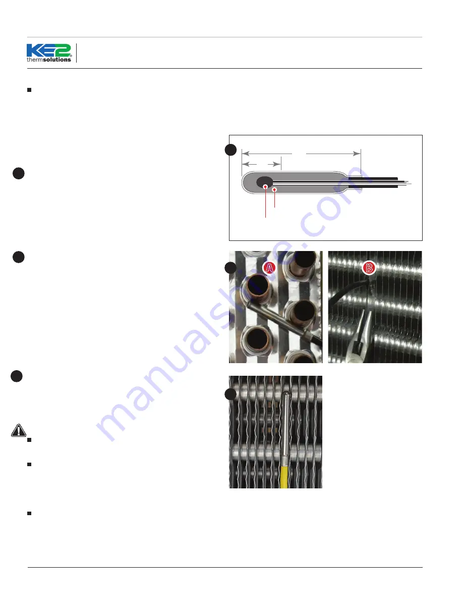
1.5”
Thermistor
Epoxy
.5”
22
23
24
Installing the Sensor Properly
Note, the most active portion of the sensor is the first 1/2” of the
1-1/2” long stainless steel probe. Figures 23 and 24 show two meth-
ods for installing the sensor in the coil. The method shown in 23 will
work in most applications, however in some cases inserting the sen-
sor into the coil may position it too close to the defrost heat source. In
these instances, the method shown in Figure 24 can be used.
22
Figure 23A shows the sensor touching two circuit tubes. When in-
serting the sensor into the coil, the tip should touch one of the cir-
cuit tubes. It should not be located adjacent to the electric heating
elements. It should be about half the distance between the heat-
ers if possible. In Figure 23B the probe is inserted into the fins ap-
proximately 1/16” deeper than the stainless shielding. Pinch the fins
gently together, securing the sensor in place. This provides thermal
ballast to ensure a complete defrost.
23
24
KE2 Adaptive
Control
Quick Start Guide


