DS-
00
2
Operation
P r o t e c t t h e m e a s u r i n g t o o l
against moisture and direct sun
light.
Do not subject the measuring
tool to extreme temperatures
or variations in temperature. In
case of large variations in tem-
perature, allow the measuring
tool to adjust to the ambient tem-
perature before switching it on.
In case of extreme temperatures
or variations in temperature, the
accuracy of the measuring tool
and the display indication can be
impaired.
Use or operation of transmitting
systems, such as WLAN, UMTS,
radar, transmitter masts or mi-
crowaves, in the close proxim-
ity can influence the measuring
function.
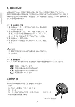
Initial Operation
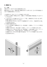
Switching On and Off
Before switching the measur-
ing tool on, make sure that the
sensor area 6 is not moist.
If re-
quired, dry the measuring tool us-
ing a soft cloth.
If the measuring tool was sub-
ject to an extreme temperature
change, allow it to adjust to the
ambient temperature before
switching on.
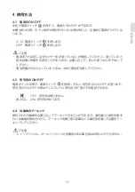
To
switch on
the measuring tool,
press the On/Off button
4
.
To
switch off
the measuring tool,
press the On/Off button
4
again.
When no button on the measuring
tool is pressed for approx. 5minutes
and when no objects are detected,
the measuring tool automatically
switches off to save the battery.
Switching the Audio Signal On/Off
When the measuring tool is switched
on, the audio signal can be switched
on or off by pressing the On/Off but-
ton
4
for a few seconds. When the
audio signal is switched off, indication
a
appears on the display.
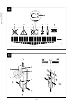
Method of Operation
(see figures A–B)
The measuring tool checks the base
material of sensor area
6
in measure-
ment direction
z
to the max. detec-
tion depth (see “Technical Data”).
Objects are detected that differ from
the material of the wall.
Always move the measuring tool in a
straight line over the surface apply-
ing slight pressure, without lifting it
off or changing the pressure. During
measurement, the contact pads
5
must always have contact to the sur-
face.
Measuring Procedure
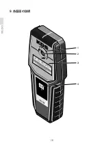
After switching on, the illuminated
ring
1
lights up green.
Position the measuring tool against
the surface being detected and move
it toward the
x
- and
y
-axis. When
the measuring tool comes closer to
an object, the amplitude in the main
scale
h
increases and ring
1
lights up
yellow; when it is moved away from
the object, the amplitude decreases.
The main scale
h
indicates the maxi-
mal amplitude above the object; ring
1
lights up red and an audio signal
sounds. For small or deeply embed-
ded objects, ring
1
can continue to
▶
▶
▶
▶
▶
Summary of Contents for EA760A-24
Page 1: ...DS 100 DS 120 Instructions DS 100 DS 120 EA760A 23A EA760A 24...
Page 2: ......
Page 3: ...DS 100 DS 120 DS 120...
Page 6: ...DS 100 DS 120 1 2 3 4...
Page 7: ...DS 100 DS 120 DS 120...
Page 8: ...DS 100 DS 120 2 3 WLAN UMTS...
Page 9: ...DS 100 DS 120 4 5...
Page 10: ...DS 100 1 9V 1 1 1 2 2 3 1 3 9V 1 2 1 2 3 4...
Page 11: ...DS 100 3 1 3...
Page 12: ...DS 100 10 3 2 OFF...
Page 13: ...DS 100 11 4 4 1 ON OFF ON OFF 5 OFF O N OFF 4 2 ON OFF ON OFF ON OFF OFF OFF ON 4 3...
Page 14: ...DS 100 12 5 5 1 ON 3 ON 1 2 3 4...
Page 15: ...DS 100 13 5 2 ON 5 1 5 3 ON 5 1 1 2 1 2 3...
Page 16: ...DS 100 14 6 1 OFF 6 2 KDS 6 3 1 3 OFF ON KDS 6 1 2 3 4 5...
Page 18: ...DS 100 16 9 1 2 3 4...
Page 19: ...DS 100 17 5 2 6 7 5 8 9 11 10 11...
Page 20: ...DS 100 18 A B a b c e f g d h i y y x x z 5 2 5 6 3x...
Page 28: ...DS 100 26 8 9 g 2 3 1 3 WLAN UMTS 6 4 4 5 4 a A B 6 z 5 1 x y h 1 h 1 1...
Page 29: ...DS 100 27 i 3x i h h x y i 1 3 d c 1 i h d c 3 e 1 2 f...
Page 30: ...DS 100 28 b 3 b h g 1 3 4 1 1 6 5...
Page 33: ...DS 100 31 4 a A B 6 z 5 1 x y h 1 h 1 1 i 3 h i h x y i 1 3 d c 1 i h d c 3 e 1...
Page 34: ...DS 100 32 2 f b 3 b h g 1 3 4 1 1...
Page 35: ...DS 100 33 6 5...
Page 36: ...DS 120 34 10 9V 10 1 10 2 2 3 1 3 9V 1 11 1 2 3 4...
Page 37: ...DS 120 35 12 1 12...
Page 38: ...DS 120 36 12 2 OFF...
Page 40: ...DS 120 38 14 14 1 ON 3 ON 1 2 3 4...
Page 41: ...DS 120 39 14 2 ON A B A B 14 1 30cm 10 3 1 2 3 4 5 1 3...
Page 43: ...DS 120 41 15 15 1 OFF 15 2 KDS 15 3 1 3 OFF KDS 1 2 3 4 5...
Page 45: ...DS 120 43 18 1 2 3 4 5 6 7 10 9 8...
Page 46: ...DS 120 44 16 18 18 11 2 12 13 11 14 15 17...
Page 47: ...DS 120 45 A B a b c d f g h e i j k B A 3x B B B 11 2 11 12...
Page 58: ...DS 120 56 i 1 i 1 1 3x j j i CENTER k i j 1 i j CENTER k 1 4 10 4 10 1 3 c 3 i j 1 10 10 12 13...
Page 59: ...DS 120 57 9 1 4 9 3 e d 1 i e d 110 230 8 1 4 8 3 f 1 2 g 3 b 4 10 3 b...
Page 60: ...DS 120 58 i h 1 3 13 12 13 5 7 1 12 11...
Page 61: ...DS 120 59 18 3 100 A CENTER 1 2 3 4 5 6 7 8 9 10 11 12 13 14 15 16 17 18 a b c d e f g h i j k...
Page 63: ...DS 120 61 5 5 6 7 a A B 12 A 11 B i 1 i 1 1 3 j i j CENTER k i j 1 i j CENTER k 1 4...
Page 64: ...DS 120 62 10 10 4 1 3 c 3 i j 1 10 10 12 13 9 1 4 3 e d 1 i e d 110 230V 8 1 4 3 f 1...
Page 65: ...DS 120 63 2 g 3 b 10 4 3 b i h 1 3 13 12 13 5 7 1...
Page 66: ...DS 120 64 12 11 17...
Page 68: ...memo...
Page 69: ...memo...
Page 70: ...memo...
Page 71: ......
Page 72: ...1 619 929 L22 DS100120 2012 06 08v1 0BO http www muratec kds jp...

