DS-
00
22
light up yellow, while there is no au-
dio signal.
Wide objects are not indicated by
the illuminated ring or the audio
signal throughout their complete
width.
As soon as the measuring tool has
localised an object below the centre
of the sensor, the fine scale
i
is acti-
vated.
To localise the object more precisely,
move the measuring tool repeatedly
(3x) back and forth over the object.
The fine scale
i
indicates a maximum
amplitude when the ob-ject is posi-
tioned precisely below the centre of
the sensor, independent thereof how
many bars are displayed in the main
scale
h
.
When very small or deeply embed-
ded objects are being sought and
main scale
h
reacts only slightly,
move the measuring tool repeatedly
over the object in horizontal (
x
-axis)
and vertical (
y
-axis) direction. Ob-
serve the amplitude of fine scale
i
.
Before drilling, sawing or rout-
ing into a wall, protect yourself
against hazards by using other
information sources.
As the meas-
uring results can be influenced
through ambient conditions or the
wall material, there may be a haz-
ard even though the indicator does
not indicate an object in the sensor
range (no audio signal or beep and
the illuminated ring
1
lit green).
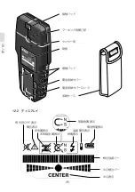
Metal
When the detected metal object is of
magnetic metal (e.g. iron), the sym-
bol
d
is indicated on display
3
. For
non-magnetic metals, the symbol
c
is indicated. In order to differentiate
between metal types, the measuring
tool must be positioned above the
detected metal object (ring
1
is lit
red and fine scale i indicates a high
amplitude).
Note:
For reinforcement steel mesh
and steel in the examined base mate-
rial, an amplitude is indicated over
the complete surface of the main
scale
h
. For reinforcement steel
mesh, it is typical that the symbol
d
for magnetic metal is indicated on
the display directly above the iron
rods, whereas between the iron rods,
the symbol
c
for non-magnetic metal
will appear.
Power Cable
When a “live” conductor is detected,
indication
e
appears on the display
3
.
Move the measuring tool repeatedly
over the area to localise the “live”
conductor more precisely. After mov-
ing over the “live” conductor several
times, it can be indicated very ac-
curately. When the measuring tool
is very close to the conductor, the
illuminated ring
1
rapidly flashes red
and the audio signal beeps swiftly.
Notes:
“Live” conductors can be detected
easier when power consumers (e.g.
lamps, machines) are connected to
the sought conductor and switched
on.
Under certain conditions (such
as below metal surfaces or be-
hind surfaces with high water
content), “live” conductors can-
not be securely detected.
The sig-
nal strength of a “live” conductor
▶
▶
-
-
Summary of Contents for EA760A-24
Page 1: ...DS 100 DS 120 Instructions DS 100 DS 120 EA760A 23A EA760A 24...
Page 2: ......
Page 3: ...DS 100 DS 120 DS 120...
Page 6: ...DS 100 DS 120 1 2 3 4...
Page 7: ...DS 100 DS 120 DS 120...
Page 8: ...DS 100 DS 120 2 3 WLAN UMTS...
Page 9: ...DS 100 DS 120 4 5...
Page 10: ...DS 100 1 9V 1 1 1 2 2 3 1 3 9V 1 2 1 2 3 4...
Page 11: ...DS 100 3 1 3...
Page 12: ...DS 100 10 3 2 OFF...
Page 13: ...DS 100 11 4 4 1 ON OFF ON OFF 5 OFF O N OFF 4 2 ON OFF ON OFF ON OFF OFF OFF ON 4 3...
Page 14: ...DS 100 12 5 5 1 ON 3 ON 1 2 3 4...
Page 15: ...DS 100 13 5 2 ON 5 1 5 3 ON 5 1 1 2 1 2 3...
Page 16: ...DS 100 14 6 1 OFF 6 2 KDS 6 3 1 3 OFF ON KDS 6 1 2 3 4 5...
Page 18: ...DS 100 16 9 1 2 3 4...
Page 19: ...DS 100 17 5 2 6 7 5 8 9 11 10 11...
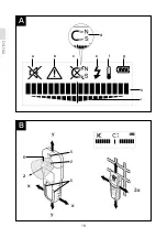
Page 20: ...DS 100 18 A B a b c e f g d h i y y x x z 5 2 5 6 3x...
Page 28: ...DS 100 26 8 9 g 2 3 1 3 WLAN UMTS 6 4 4 5 4 a A B 6 z 5 1 x y h 1 h 1 1...
Page 29: ...DS 100 27 i 3x i h h x y i 1 3 d c 1 i h d c 3 e 1 2 f...
Page 30: ...DS 100 28 b 3 b h g 1 3 4 1 1 6 5...
Page 33: ...DS 100 31 4 a A B 6 z 5 1 x y h 1 h 1 1 i 3 h i h x y i 1 3 d c 1 i h d c 3 e 1...
Page 34: ...DS 100 32 2 f b 3 b h g 1 3 4 1 1...
Page 35: ...DS 100 33 6 5...
Page 36: ...DS 120 34 10 9V 10 1 10 2 2 3 1 3 9V 1 11 1 2 3 4...
Page 37: ...DS 120 35 12 1 12...
Page 38: ...DS 120 36 12 2 OFF...
Page 40: ...DS 120 38 14 14 1 ON 3 ON 1 2 3 4...
Page 41: ...DS 120 39 14 2 ON A B A B 14 1 30cm 10 3 1 2 3 4 5 1 3...
Page 43: ...DS 120 41 15 15 1 OFF 15 2 KDS 15 3 1 3 OFF KDS 1 2 3 4 5...
Page 45: ...DS 120 43 18 1 2 3 4 5 6 7 10 9 8...
Page 46: ...DS 120 44 16 18 18 11 2 12 13 11 14 15 17...
Page 47: ...DS 120 45 A B a b c d f g h e i j k B A 3x B B B 11 2 11 12...
Page 58: ...DS 120 56 i 1 i 1 1 3x j j i CENTER k i j 1 i j CENTER k 1 4 10 4 10 1 3 c 3 i j 1 10 10 12 13...
Page 59: ...DS 120 57 9 1 4 9 3 e d 1 i e d 110 230 8 1 4 8 3 f 1 2 g 3 b 4 10 3 b...
Page 60: ...DS 120 58 i h 1 3 13 12 13 5 7 1 12 11...
Page 61: ...DS 120 59 18 3 100 A CENTER 1 2 3 4 5 6 7 8 9 10 11 12 13 14 15 16 17 18 a b c d e f g h i j k...
Page 63: ...DS 120 61 5 5 6 7 a A B 12 A 11 B i 1 i 1 1 3 j i j CENTER k i j 1 i j CENTER k 1 4...
Page 64: ...DS 120 62 10 10 4 1 3 c 3 i j 1 10 10 12 13 9 1 4 3 e d 1 i e d 110 230V 8 1 4 3 f 1...
Page 65: ...DS 120 63 2 g 3 b 10 4 3 b i h 1 3 13 12 13 5 7 1...
Page 66: ...DS 120 64 12 11 17...
Page 68: ...memo...
Page 69: ...memo...
Page 70: ...memo...
Page 71: ......
Page 72: ...1 619 929 L22 DS100120 2012 06 08v1 0BO http www muratec kds jp...

