DS-
20
5
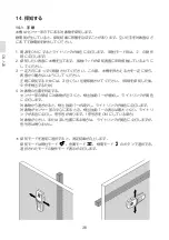
mesh, it is typical that the symbol
e
for magnetic metal is indicated on
the display directly above the iron
rods, whereas between the iron rods,
the symbol
d
for non-magnetic metal
will appear.
Power Cable
The operating mode
“Power cable”
is suitable only for detecting "live"
conductors (0–230V).
Press button
8
to activate the op-
erating mode
“Power cable”
. The
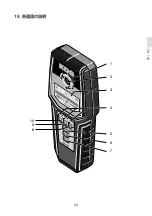
illuminated ring
1
and indication
4
above button
8
light up green.
When a “live” conductor is detected,
indication
f
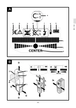
appears on the display
3
. Move the measuring tool repeat-
edly over the area to localise the
“live” conductor more precisely.
After moving over the “live” conduc-
tor several times, it can be indicated
very accurately. When the measuring
tool is very close to the conductor,
the illuminated ring
1
flashes red and
the audio signal beeps swiftly.
Notes:
“Live” conductors are indicated in
any operating mode.
“Live” conductors can be detected
easier when power con-sumers
(e.g. lamps, machines) are con-
nected to the sought conductor
and switched on.
Under certain conditions (such
as below metal surfaces or be-
hind surfaces with high water
content), “live” conductors can-
not be securely detected.
The sig-
nal strength of a “live” conductor
depends on the position of the ca-
ble. Therefore, apply further meas-
urements in close proximity or use
other information sources to check
if a “live” conductor exists.
Voltage-free conductors can be de-
tected as metal objects in the op-
eration mode
“Metal”
. This does
not apply for stranded conductors
(contrary to solid conductors or
cable).
Static electricity can lead to inac-
curate indication of electric lines,
e.g., over a large range. To improve
the indication, place your free hand
flat on the wall next to the meas-
uring tool, in order to remove the
static electricity.
Working Advice
Measuring values can be im-
paired through certain ambient
conditions. These include, e.g.,
the proximity of other equipment
that produce strong magnetic or
electromagnetic fields, moisture,
metallic building materials, foil-
laminated insulation materials
or conductive wallpaper or tiles.
Therefore, please also observe
other information sources (e.g.
construction plans) before drilling,
sawing or routing into walls, ceil-
ings or floors.
Marking Objects
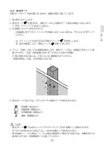
If required, detected objects can
be marked. Perform a measure-
ment as usual. Once you have found
the boundaries or the centre of an
object, mark the sought location
through the marking hole
2
.
-
-
-
-
-
▶
Summary of Contents for EA760A-24
Page 1: ...DS 100 DS 120 Instructions DS 100 DS 120 EA760A 23A EA760A 24...
Page 2: ......
Page 3: ...DS 100 DS 120 DS 120...
Page 6: ...DS 100 DS 120 1 2 3 4...
Page 7: ...DS 100 DS 120 DS 120...
Page 8: ...DS 100 DS 120 2 3 WLAN UMTS...
Page 9: ...DS 100 DS 120 4 5...
Page 10: ...DS 100 1 9V 1 1 1 2 2 3 1 3 9V 1 2 1 2 3 4...
Page 11: ...DS 100 3 1 3...
Page 12: ...DS 100 10 3 2 OFF...
Page 13: ...DS 100 11 4 4 1 ON OFF ON OFF 5 OFF O N OFF 4 2 ON OFF ON OFF ON OFF OFF OFF ON 4 3...
Page 14: ...DS 100 12 5 5 1 ON 3 ON 1 2 3 4...
Page 15: ...DS 100 13 5 2 ON 5 1 5 3 ON 5 1 1 2 1 2 3...
Page 16: ...DS 100 14 6 1 OFF 6 2 KDS 6 3 1 3 OFF ON KDS 6 1 2 3 4 5...
Page 18: ...DS 100 16 9 1 2 3 4...
Page 19: ...DS 100 17 5 2 6 7 5 8 9 11 10 11...
Page 20: ...DS 100 18 A B a b c e f g d h i y y x x z 5 2 5 6 3x...
Page 28: ...DS 100 26 8 9 g 2 3 1 3 WLAN UMTS 6 4 4 5 4 a A B 6 z 5 1 x y h 1 h 1 1...
Page 29: ...DS 100 27 i 3x i h h x y i 1 3 d c 1 i h d c 3 e 1 2 f...
Page 30: ...DS 100 28 b 3 b h g 1 3 4 1 1 6 5...
Page 33: ...DS 100 31 4 a A B 6 z 5 1 x y h 1 h 1 1 i 3 h i h x y i 1 3 d c 1 i h d c 3 e 1...
Page 34: ...DS 100 32 2 f b 3 b h g 1 3 4 1 1...
Page 35: ...DS 100 33 6 5...
Page 36: ...DS 120 34 10 9V 10 1 10 2 2 3 1 3 9V 1 11 1 2 3 4...
Page 37: ...DS 120 35 12 1 12...
Page 38: ...DS 120 36 12 2 OFF...
Page 40: ...DS 120 38 14 14 1 ON 3 ON 1 2 3 4...
Page 41: ...DS 120 39 14 2 ON A B A B 14 1 30cm 10 3 1 2 3 4 5 1 3...
Page 43: ...DS 120 41 15 15 1 OFF 15 2 KDS 15 3 1 3 OFF KDS 1 2 3 4 5...
Page 45: ...DS 120 43 18 1 2 3 4 5 6 7 10 9 8...
Page 46: ...DS 120 44 16 18 18 11 2 12 13 11 14 15 17...
Page 47: ...DS 120 45 A B a b c d f g h e i j k B A 3x B B B 11 2 11 12...
Page 58: ...DS 120 56 i 1 i 1 1 3x j j i CENTER k i j 1 i j CENTER k 1 4 10 4 10 1 3 c 3 i j 1 10 10 12 13...
Page 59: ...DS 120 57 9 1 4 9 3 e d 1 i e d 110 230 8 1 4 8 3 f 1 2 g 3 b 4 10 3 b...
Page 60: ...DS 120 58 i h 1 3 13 12 13 5 7 1 12 11...
Page 61: ...DS 120 59 18 3 100 A CENTER 1 2 3 4 5 6 7 8 9 10 11 12 13 14 15 16 17 18 a b c d e f g h i j k...
Page 63: ...DS 120 61 5 5 6 7 a A B 12 A 11 B i 1 i 1 1 3 j i j CENTER k i j 1 i j CENTER k 1 4...
Page 64: ...DS 120 62 10 10 4 1 3 c 3 i j 1 10 10 12 13 9 1 4 3 e d 1 i e d 110 230V 8 1 4 3 f 1...
Page 65: ...DS 120 63 2 g 3 b 10 4 3 b i h 1 3 13 12 13 5 7 1...
Page 66: ...DS 120 64 12 11 17...
Page 68: ...memo...
Page 69: ...memo...
Page 70: ...memo...
Page 71: ......
Page 72: ...1 619 929 L22 DS100120 2012 06 08v1 0BO http www muratec kds jp...


