9
z
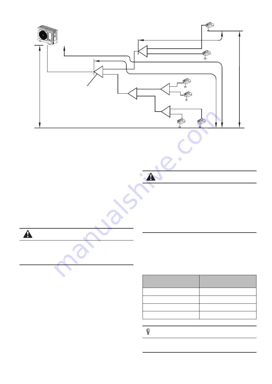
The second cennect methond
Indoor unit
a
N
1
3
N
N
5
N
6
N
2
N
4
Outdoor unit
A
B
D
E
C
b
c
e
f
d
1
L
2
L
5
L
3
L
4
L
Drop HEIGHT
between indoor unit and uutdoor unit
Maximum pipe equivalent length
Pipe length(From the nearest branch
pipe equivalent length
(From the first line branch pipe)
Maximum pipe equivalent length
Indoor Unit to Indoor Unit Drop Heihg
t
The First Line Branch Pipe
Fig.4-8
4.7 Remove Dirt or Water in the Piping
Make sure there is no any dirt or water before connectiong the piping
to the outdoor units.
Wash the piping with high pressure nitrogen, never use refrigerant of
outdoor unit.
4.8 Airtight Test
Air tightness test – nitrogen must be used. (See the fgure on the right
for the location of the maintenance access).
Increase the pressure from the liquid pipe and gas pipe to 4.0 MPa at
the same time (not exceeding 4.0 MPa). If the pressure does not drop
in 24 hours, the test is passed.
When the pressure drops, check the leakage position (after
you make sure that there is no leakage, discharge the nitrogen).
CAUTION
Never use oxygen, combustible gas, or poisonous gas in the air
tightness test.
To prevent damage to the equipment, the pressure must not be
held for too long.
4.9 Air Purge with Vacuum Pump
z
Use a vacuum pump that can evacuate the pipe to the pressure
of less than -100.7 kPa (5 Torr, -755mmHg). When the pump is
stopped, do not let the pump oil fow back into the refrigerant pipe.
z
The liquid and gas pipes should be evacuated with a vacuum pump
for more than two hours to the pressure of less than - 100.7kPa.
Then, place the pipes with the pressure of less than -100.7 kPa for
more than one hour, and check whether the reading of the vacuum
gauge rises. (If the reading rises, there is residual water or gas
leakage in the system. The leakage must be checked and solved
and the test should be performed again.)
z
Water may enter into pipes in the following conditions: the
installation is carried out in rainy seasons and the installation
period is long; the pipes are condensed inside; rainwater enters the
pipes.
z
After the above vacuum drying of two hours, use nitrogen to
increase the pressure to 0.05 MPa (vacuum breaking), and use a
vacuum pump to decrease the pressure to lower than -100.7kPa or
below and hold the pressure for one hour (vacuum drying).
(If the pressure cannot be decreased to lower than -100.7 kPa after
two-hour vacuumizing, repeat the vacuum breaking and vacuum
process.) After that, place the vacuum pipes for one hour, and then
check whether the reading of the vacuum gauge rises.
CAUTION
Use a vacuum pump to perform the vacuumizing process. Do not
use refrigerant gas to discharge air.
Use a vacuum pump that can vacuumize the pipe to the pressure
of less than -100.7 kPa (5 Torr, -755 mmHg). When the pump is
stopped, do not let the pump oil fow back into the refrigerant pipe.
In order to prevent the entry of impurities, the R410A special tool
must be used to ensure the compression strength. Use a flling
hose with a top rod to connect to the maintenance access of the
check valve or the refrigerant flling port.
4.10 Refrigerant Amount to be Added
Calculate the amount of the R410A refrigerant to be added based on
the diameter and length of the liquid pipes of the ODU and IDUs.
When the outdoor unit connects 1 indoor unit:
Table 4-12
Liquid Side Piping Diameter
Refrigerant to be Added
Permeter Piping
Φ6.4
0.022kg
Φ9.5
0.054kg
Φ12.7
0.110kg
Φ15.9
0.170kg
NOTE
Additional refrigerant volume of divergent pipe is 0.1kg per item
(Consider the liquid side of divergent pipe only)
Summary of Contents for KMF-120 DVN4
Page 16: ......


