background image

ERGOcom 3

5 Operation

 | 

5.3 Operation, with display interface (comfort/excellence)

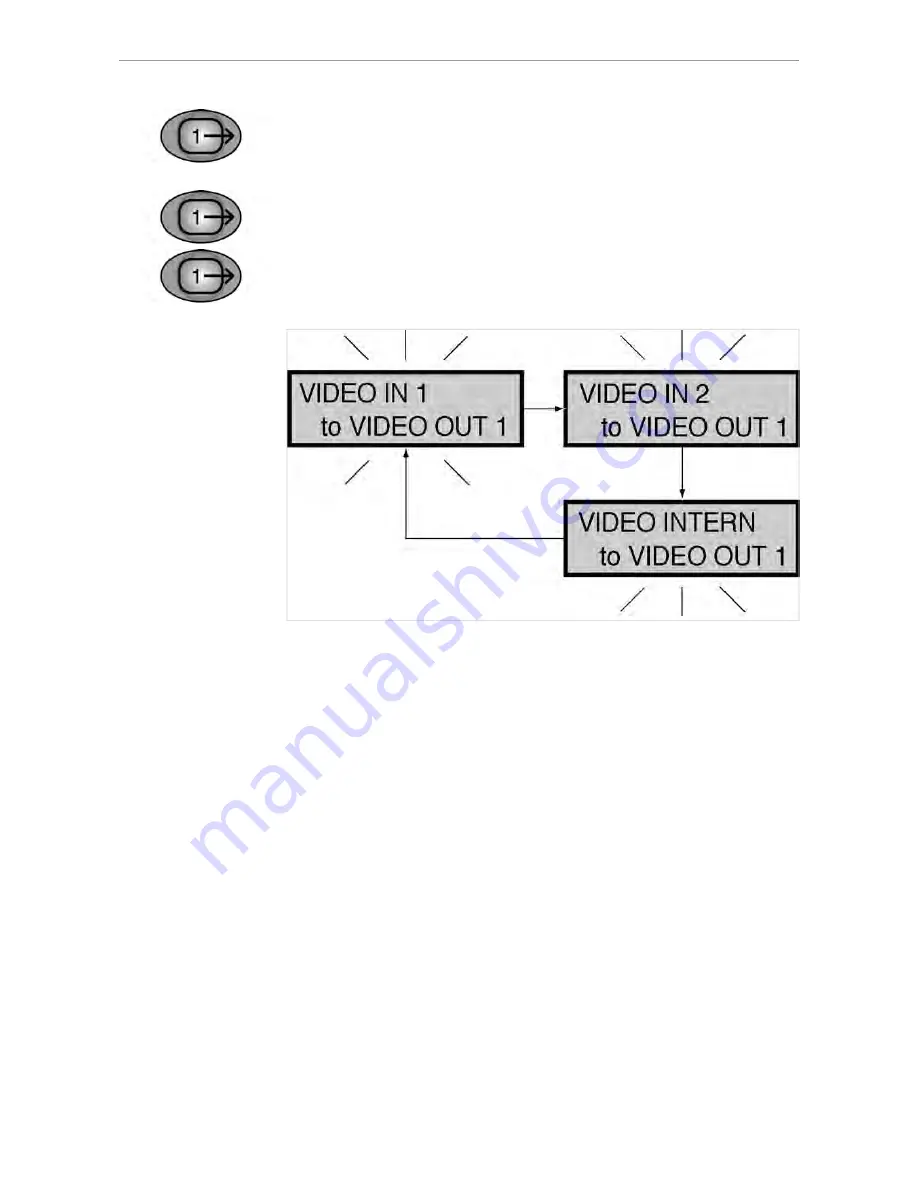
▶ Hold down the VIDEO OUT 1 button for < 2 seconds.

The last image source selected is shown in the status display. The status display

returns to operational mode after 5 seconds.

▶ Hold down VIDEO OUT 1 for > 2 seconds.

The status display flashes and setting mode is activated.

▶ Select the required VIDEO input by pressing the VIDEO OUT 1 button.

39/56

Summary of Contents for ERGOcom 3

Page 1: ...Annex No 5 Technical Description Users Manual...

Page 2: ...User instructions ERGOcom 3 Always on the safe side...

Page 3: ...trieb Distribution KaVo Dental GmbH Co KG Bahnhofstra e 20 D 88447 Warthausen Tel 49 73 51 56 0 Fax 49 73 51 56 16 27 Hersteller Manufacturer Kaltenbach Voigt GmbH Co KG Bismarckring 39 D 88400 Bibera...

Page 4: ...t specific 13 2 3 Safety instructions 14 2 3 1 General 14 2 3 2 Product specific 14 3 Product description 15 3 1 Product name 15 3 2 ERGOcom 3 16 3 3 Connections 17 3 4 Rating plate 18 3 5 Technical d...

Page 5: ...hange display view 42 5 3 9 Select image 43 5 3 10 Delete image images 44 5 3 11 Change image source 45 5 4 Operation OSD menu display interface 46 5 4 1 Call OSD menu display interface 46 5 4 2 Opera...

Page 6: ...isite Please read these instructions before using the product to avoid operator error and damage 1 1 1 Abbreviations Abbre viation Meaning UI User instructions SI Setup instructions EI Engineer s inst...

Page 7: ...ERGOcom 3 1 User Notes 1 2 Target audience 1 2 Target audience This document is intended for use by dentists and other dental practice employees 6 56...

Page 8: ...12 60389 Frankfurt 069 5 97 03 94 95 KaVo Pr sentations und Servicezentrum Hamburg KaVo Presentation and Service Center Hamburg Sachsenstra e 5 20097 Hamburg 040 23 44 77 78 KaVo Pr sentations und Ser...

Page 9: ...ing legal provisions opposing it KaVo shall not be liable for defects and their consequences which occur as a result ofnormal wear and tear or of improper cleaning or maintenance Non observance of the...

Page 10: ...recipient must record the loss or damage on the notice of receipt The reci pient and transport company employee delivering the product must both sign the notice of receipt 2 Leave the product and pack...

Page 11: ...the product is damaged without there being any noticeable damage to the packa ging upon delivery you must proceed as follows 1 As soon as possible within 7 days of delivery report the damage to the tr...

Page 12: ...ERGOcom 3 1 User Notes 1 5 Transport and storage Stacking limitation Temperature limitations 11 56...

Page 13: ...n of the different levels of hazard To avoid personal and material injury safety instructions within this document are classified into three levels of hazard CAUTION CAUTION Indicates a potentially da...

Page 14: ...laws national regulations and technlogical rules for starting up and operating have to be applied and fulfilled in line with the specified intended purpose of the KaVo product Note It is mandatory th...

Page 15: ...ions of implanted systems such as pacemakers Consult the patient before treatment This KaVo product is not permitted for use in areas where there is a risk of explosion The following individuals are a...

Page 16: ...rd to the components built in among other things Model Components classic No display interface No radio master ERGOremote comfort With display interface No radio master ERGOremote excellence With disp...

Page 17: ...lue 11 Navigation right 3 Standby 12 Navigation down 4 Button VGA In 1 In 2 13 Delete image images 5 Button Video Camera In 2 In 3 14 Freeze 6 Status display 15 Button Video Out 2 7 OSD menu 16 Button...

Page 18: ...15 Mains fuse 4 Video In 2 16 Power supply monitor 5 Audio Out 1 17 Display 1 connection 6 Video Out 1 18 Camera connection 7 Audio Out 2 19 USB downstream 8 Video Out 2 20 USB upstream 9 Audio VGA In...

Page 19: ...4 Rating plate 3 4 Rating plate SN Serial number REF Material number Type Device typeERGOcom 3 HF emission Note consult accompanying documents VDE identification CE identification Consult instructions...

Page 20: ...ng dimensions Width 260 mm Depth 260 mm Height 46 5 mm Electricity supply AC voltage 100 240 V Rated frequency 50 60 Hz Power consumption 70 VA Ambient conditions Permissible operating temperature 0 4...

Page 21: ...ntal Connect theERGOcom 3 to a properly earthed power source that is protected by a fuse 4 1 2 Start up radio receiving Select channel Here up to 38 channels can be set A channel determines the assign...

Page 22: ...e Wake Up Learn button on the ERGOremote for more than 3 se conds The green LED will be lit for 3 seconds to show that synchronisation is complete The green LED will flash to indicate that radio commu...

Page 23: ...ree USB 2 interface Install Windows patch Note When installing theKaVo Device Interface System using the enclosed CD the USB patch is installed automatically If the KaVo Device Interface System is not...

Page 24: ...bmp to the USB drive using the drag drop function The USB drive reports to the PC using the name ERGOCOM3 Note The ERGOcom 3 must not be switched off during transfer of the image takes approx 20 secon...

Page 25: ...blue The status display and display are switched off and all device settings are retai ned Press the standby button once again to leave Standby mode Note This energy saving mode extends the service li...

Page 26: ...rface Material number 1 002 9482 wlink represents component radio master Material number 1 003 1318 OK represents the installation of the relevant option Missing components can be added at any time Se...

Page 27: ...rmining the image format in which the images are to be saved to the USB drive BMP stands for bitmap and is supported by all popular image processing programs The current YUV format is converted to BMP...

Page 28: ...ion on Display 1 the relevant source must be active 5 2 1 Operational mode In operational mode it is possible to switch between VGA or VIDEO image sources including audio shown on KaVo Display 1 VGA I...

Page 29: ...ource Prerequisite A grabber card has to be installed in the PC in order to show video sources on Display 1 VIDEO OUT 1 or VIDEO OUT 2 has to be connected to the grabber card Press the VIDEO IN button...

Page 30: ...DEO input by pressing the VIDEO IN button See also 5 4 5 Menu point other Page 49 5 2 2 VGA OUT set image source Hold down the VGA OUT button for 2 seconds The last image source selected is shown in t...

Page 31: ...the VGA OUT button for 2 seconds The status display flashes and setting mode is activated Use VGA OUT to select the required VGA input Note If there is no input for 8 seconds the ERGOcom 3 switches b...

Page 32: ...ay returns to operational mode after 5 seconds See also 5 2 1 Operational mode Page 27 Hold down VIDEO OUT 1 for 2 seconds The status display flashes and setting mode is activated Select the required...

Page 33: ...ds The last image source selected is shown in the status display The status display returns to operational mode after 5 seconds See also 5 2 1 Operational mode Page 27 Hold down the VIDEO OUT 2 button...

Page 34: ...ted to a PC fitted with a grabber card by means of a USB cable On this PC the KaVo Display Interface System software is installed Hold down the footswitch for 2 seconds The Generate still command is p...

Page 35: ...ERGOcom 3 5 Operation 5 2 Operation no display interface classic 5 2 7 Audio signals The audio signals will be linked synchronously to the relevant image signals 34 56...

Page 36: ...in the separate UI See also UIERGOremote In all subsequent descriptions please note the following to view the selected option on Display 1 the relevant source must be active 5 3 1 Operational mode In...

Page 37: ...n Note If no image source is connected to VIDEO IN 1 2 the logo set in the OSD menu display interface will be displayed See also 5 4 5 Menu point other Page 49 VIDEO IN set image source Press the VIDE...

Page 38: ...image source is connected to VIDEO IN 1 2 the logo set in the OSD menu display interface will be displayed See also 5 4 5 Menu point other Page 49 5 3 2 VGA OUT set image source Hold down the VGA OUT...

Page 39: ...d down the VGA OUT button for 2 seconds The status display flashes and setting mode is activated Use VGA OUT to select the required VGA input Note If there is no input for 8 seconds the ERGOcom 3 swit...

Page 40: ...on for 2 seconds The last image source selected is shown in the status display The status display returns to operational mode after 5 seconds Hold down VIDEO OUT 1 for 2 seconds The status display fla...

Page 41: ...seconds The last image source selected is shown in the status display The status display returns to operational mode after 5 seconds See also 5 2 1 Operational mode Page 27 Hold down the VIDEO OUT 2...

Page 42: ...ill be linked synchronously to the relevant image signals 5 3 6 Generate still Prerequisite A video signal is shown on Display 1 Hold down the Freeze button for 2 seconds A still is generated on Displ...

Page 43: ...nds The successful save is indicated on Display 1 with save or Hold down the footswitch for 2 seconds The successful save is indicated on Display 1 with save Note Saving the active image image number...

Page 44: ...selected must be a still Select the required image using the 4 navigation buttons The still selected is retained as a still Press the Freeze button The still selected is deleted or turned into a live...

Page 45: ...nt other Page 49 Hold down the Delete image images button for 2 seconds All 4 stills are deleted and the logo selected in the OSD menu display interface is shown Multi footswitch control Prerequisite...

Page 46: ...omfort excellence 5 3 11 Change image source Prerequisite A still has to be generated See also 5 3 6 Generate still Page 41 Put the camera in the holder Press the footswitch TheERGOcom 3 switches to t...

Page 47: ...menu display interface Prerequisite The image source for which the display settings are to be changed must be selec ted See also 5 2 1 Operational mode Page 27 5 3 1 Operational mode Page 35 Press the...

Page 48: ...ting Reset the selected menu point 5 4 3 VGA main menu There is a separate main menu for every VGA IN image source This allows the settings on Display 1 to be defined and saved for every image source...

Page 49: ...O main menu There is a separate main menu for every VIDEO IN image source This allows the settings on Display 1 to be defined and saved for every image source Note The requisite explanations of the in...

Page 50: ...u point other This menu point is available in all main menus VGA and VIDEO However it is not saved separately for all menus but only once covering all menus Note The requisite explanations of the indi...

Page 51: ...ERGOcom 3 5 Operation 5 4 Operation OSD menu display interface 50 56...

Page 52: ...ket As damage to surfaces is very much dependent on the reaction times of these sub stances it is essential for any spilled substances to be wiped away immediately using a damp cloth Detergent recomme...

Page 53: ...6 2 Disinfection CAUTION Damage caused by fluids Faults in electrical components Protect device openings from the penetration of fluids Wipe surface with a soft fluff free cloth to disinfect them Note...

Page 54: ...ERGOcom 3 6 Preparation methods DIN EN ISO 17664 6 3 Maintenance 6 3 Maintenance The product does not require regular user maintenance 53 56...

Page 55: ...ecks 7 Safety checks If an EC3 Display is integrated with an ERGOcom 3 safety checks SFC must be performed every 2 years A detailed description of SFC can be found in the engineer s instructions See a...

Page 56: ...not installed on the target computer Install the required patch This can be done while installing the CCCDIS See also 4 1 3 Connect PC Page 22 Selected image source e g DVD player is not displayed The...

Page 57: ...l screen mode The image is displayed across the entire display area Quad mode Four independent images are shown in the display OSD menu display inter face The OSD menu of the display interface This is...

Page 58: ......

Page 59: ...1 003 1609 Ma 08 04 01 EN...

Page 60: ...User instructions ERGOremote Always on the safe side...

Page 61: ...Sales and Distribution KaVo Dental GmbH Bismarckring 39 D 88400 Biberach Tel 49 73 51 56 0 Fax 49 73 51 56 14 88 Manufacturer Kaltenbach Voigt GmbH Bismarckring 39 D 88400 Biberach...

Page 62: ...specific 10 2 3 Safety instructions 11 2 3 1 General 11 3 Product description 12 3 1 ERGOremote 12 3 2 Rating plate 13 3 3 Technical data 14 4 Start up 15 4 1 Insert battery 15 4 2 Learn channel 16 5...

Page 63: ...User instructions ERGOremote Table of contents 6 Preparation methods DIN EN ISO 17664 22 6 1 Cleaning 22 6 1 1 Exterior cleaning by hand 22 6 2 Disinfection 23 6 3 Maintenance 24 7 Glossary 25 2 25...

Page 64: ...Service Technician s instructions SFC Safety checks IEC International Electrotechnical Commission 1 1 2 Symbols See Safety Hazard Warning Symbol chapter Important information for users and Service Te...

Page 65: ...User instructions ERGOremote 1 User Notes 1 2 Target audience 1 2 Target audience This document is intended for use by dentists and other dental practice employees 4 25...

Page 66: ...Ser vice Center Frankfurt Hungener Stra e 6 12 60389 Frankfurt 069 5 97 03 94 95 KaVo Pr sentations und Servicezentrum Hamburg KaVo Presentation and Ser vice Center Hamburg Sachsenstra e 5 20097 Hamb...

Page 67: ...com pelling legal provisions opposing it KaVo shall not be liable for defects and their consequences which occur as a result of normal wear and tear or of improper cleaning or maintenance Non observa...

Page 68: ...ging is noticeably damaged upon delivery the following procedure must be adhered to 1 The recipient must record the loss or damage on the notice of receipt The reci pient and transport company employe...

Page 69: ...is damaged without there being any noticeable damage to the packa ging upon delivery you must proceed as follows 1 Report the damage to the transport company as soon as possible within 7 days of deliv...

Page 70: ...Description of the different levels of hazard To avoid personal and material injury safety instructions within this document are classified into three levels of hazard CAUTION CAUTION Indicates a pote...

Page 71: ...with the specified intended purpose of the KaVo product Note Dispose of or recycle the waste materials produced without endangering human health or the environment and under observance of the applicab...

Page 72: ...ones and medical devi ces it is not however possible to completely exclude the possibility of the product being affected by a functioning mobile phone Refrain from using mobile phones in the practice...

Page 73: ...mage Call ERGOcom 3 Con trol 10 Standby On 2 LED Radio Communication 11 VGA Input 1 to Display 1 3 Wake Up Learn 12 Video Input 1 to Display 1 4 Freeze 13 Video Input Camera to Display 1 5 Mouse Joyst...

Page 74: ...User instructions ERGOremote 3 Product description 3 2 Rating plate 3 2 Rating plate Type ERGOremote Purchase order no 1 003 0539 Serial no nnnnnn DL123 Battery and polarity labelling 13 25...

Page 75: ...aximum range without obstructions typically 100 m Range in room 20 m Radiated power 5 mW Sleep mode 10 A Standby typically 3 mA Send operation typically 100 mA Receive operation typically 80 mA EN 300...

Page 76: ...nsert battery Note A DL 123 battery is supplied with the equipment Only use original batteries We cannot provide a functional guarantee for other batteries Remove screw to open battery compartment Ins...

Page 77: ...than 2 se conds Learn Channel Mode appears on the status display Note If the channels do not synchronise within approx 30 seconds ERGOcom 3 swit ches back to operational mode Hold down the Wake Up Lea...

Page 78: ...the Wake Up button or any other function button apart from the joystick The LED is lit up for approx 3 seconds An internal calibration is run during this period The joystick must not be moved about A...

Page 79: ...e is active Press delete The active image in Quad or Full Screen mode is deleted 5 1 7 Quad mode in Video mode You use this button to toggle between Full Screen and Quad mode 5 1 8 Freeze in Video mod...

Page 80: ...ick functions by placing axial pressure on the joystick Up In VGA mode the up button is used to scroll through active menus In Video mode and OSD Display Interface mode it can be used to navigate bet...

Page 81: ...ideo Input 1 to Display 1 This button is used to switch the incoming image signal at Video 1 directly to Display 1 5 1 14 VGA Input 2 to Display 1 This button is used to switch the associated image co...

Page 82: ...mote 5 Operation 5 1 Controls displays If the cell voltage falls below the level required for safe operation the red LED will flash for approximately 3 seconds after wake up indicating that the batter...

Page 83: ...tances available on the market As damage to surfaces is very much dependent on the reaction times of these sub stances it is essential for any spilled substances to be wiped away immediately using a d...

Page 84: ...ethods DIN EN ISO 17664 6 2 Disinfection 6 2 Disinfection CAUTION Damage caused by fluids Faults in electrical components Protect product openings from the penetration of fluids Wipe surface with a so...

Page 85: ...User instructions ERGOremote 6 Preparation methods DIN EN ISO 17664 6 3 Maintenance 6 3 Maintenance The product does not require regular user maintenance 24 25...

Page 86: ...ce Full screen mode The image is displayed across the entire display area Quad mode Four independent images are shown in the display OSD menu display inter face The OSD menu of the display interface T...

Page 87: ......

Page 88: ...1 003 1631 hw 31 01 2005 02 en...

Reviews: