background image

-4-

        (3) 維修工作時。
        (4) 離開工作場所或工作場所無人看顧
            時。

     8. 假如不慎讓機器及配件使用之油或油
        脂,接觸到眼睛、皮膚貨誤食時,請立
        刻以水清洗接觸部位及就診。

     9. 請勿擅自碰觸運轉中之零件或配件及
        注意機器電源是否已開啟,以免導致人


員受傷。

    10. 維修、修改及調整等工作,須由受過
        適當訓練的技師或熟手為之。維修時只
        許使用指定之零件。

    11. 一般維修及檢查工作必須由受過適當
        訓練的人員為之。

    12. 電子零件維修及保養工作必須由資深
        的電子技師為之,或由非常熟練的人員
        檢查及指導,當發現零件損壞時,請立
        刻停止機器運轉。

    13. 在做裝有氣動式零件 ( 例如氣缸 )
        機器的維修及保養工作前,機器連接
        空壓機及高壓空氣必須予以關閉及卸
        除,機器中殘存高壓氣體必須予以消
        除,此外調整及性能檢查只能由受過
        適當訓練的技師或熟手為之。

    14. 機器使用一段時間,必須定期清理。

           (3) When repairing.
           (4) When the operator leaves the 
                 working place or leaves the 
                 machine unattended.
       8. If grease, oil, or any fluid contacts 
           your skin or eyes by any chance, 
           please wash the contacted area 
           completely with clean water and 
           consult a doctor. Or, swallow any fluid 
           mistakenly, consult a doctor 
           immediately.
       9. Do not touch any functioning parts 
           and devices. Always attend to 
           whether power switch is on or off 
           before operating in order to prevent 
           anyone from getting hurts.
       10. Qualified technicians are required 
            for adjustment, modification, and 
            repair. Only use assigned parts for 
            replacement.
       11. Routine maintenance and service 
            must be performed by well trained 
            persons, or qualified technicians.
       12. Maintain and check the electronic 
            parts must be done by qualified 
            electrician or well-trained persons. If 
            any electronic part damaged or 
            malfunctioned, stop the machine 
            immediately.
       13. The air house has to be detached 
            from the machine and the 
            compressor or air supply has to be 
            cut off before repairing and servicing 
            the machine equipped with 
            pneumatic parts such as an air 
            cylinder. Qualified technicians or 
            well-trained persons are required for 
            adjustment and repairs.


14. To ensure the best performance, 

            periodically clean the machine is 
            necessary.

Summary of Contents for Siruba LF-D6

Page 1: ...LF D6 使用說明書與零件圖 INSTRUCTION BOOK PARTS LIST ...

Page 2: ......

Page 3: ...g maintenance 如果忽視此標記而運行了錯誤的機械操作 保養時有可能會引起 當事者或第三者人員受傷及造成設備損壞 Ignoring this warning sign and proceed incorrect operation will cause the person involved or the third party wounded and equipment damaged during maintenance 運動部位 謹防工傷事故 Moving part beware of industrial accident 高壓部位 謹防觸電事故 High voltage beware of electric shock 高溫部位 謹防燙傷事故 High temperature beware of burns 禁止 Prohibited 地線的接線表示 Indicatio...

Page 4: ...MPORTANT SAFETY INSTRUCTION WARNING SPECIFICATIONS COMBINATION POWER WIRING DIAGRAM WIRING DIAGRAM AC 220V WIRE CONNECTION D6 DEVICE ADJUSTMENTS THE ILLUSTRATION OF THE CONTROL PANEL THE ILLUSTRATION OF THE PARAMETERS OPERATION GUIDE TROUBLESHOOTING SIMPLE REPAIR PARTS LIST TABLE CUT OUT OF 747S T5 1 3 7 7 8 9 10 11 11 15 17 20 24 28 29 35 ...

Page 5: ...et visitors touch the tool or extension code 5 Dress properly Do not wear loose clothing or jewelry they can be caugh in moving parts Wear protecting hair covering to contain long hair 6 Do not abuse the cord Never carry the machine by cord or yank it to disconnect it from the socket Keep the cord away from heat oil and sharp edges 7 Maintain machine with care Follow instructions for lubrication a...

Page 6: ...urther use of the tool a guard or other part that is damaged should be carefully checked to determine that it will operate properly and perform its intended function 11 Warning The use of any accessory or attachment other than those recommended in this instruction manual may present a risk of personal injury 12 Have your tool repaired by a qualified person Repairs should only be carried out by qua...

Page 7: ... instructions when you use this machine please pay attention to the basic safety measures 2 Before using this machine please read this manual and all related instructions In addition please keep this manual for future needs 3 Before using this machine please ascertain that it conforms with safety standards and regulations of your country 4 When the machine is ready for operation all the safety equ...

Page 8: ...nctioning parts and devices Always attend to whether power switch is on or off before operating in order to prevent anyone from getting hurts 10 Qualified technicians are required for adjustment modification and repair Only use assigned parts for replacement 11 Routine maintenance and service must be performed by well trained persons or qualified technicians 12 Maintain and check the electronic pa...

Page 9: ... uses of this machine are not allowed 18 Any modification or conversion made on this machine must be conformed with the safety standards and regulations Precaution is necessary No responsibility will our company take for damages caused by any modification or conversion of this machine without permission 19 Two safety warning signs are applied as warning signs 1 For the safety of operators and serv...

Page 10: ...wer of the machine while changing bobbins e Be careful and do not place your fingers inside the machine when placing or lifting the machine head to avoid possible physical injuries f Please turn off the power before tilting the machine head to avoid possible accidents due to abrupt start of this machine g For machine equipped servo motors the motors do not produce noise while the machines are at r...

Page 11: ...pply 5 Never use the machine when the local voltage type is different from the marked voltage on the nametag attached on the machine 6 Confirm that the rotating direction of the machine pulley is correct Warning Before doing any operation or any adjustment described later in this manual please turn the power off to prevent accidents caused by abrupt start of the sewing machine 為了避免機器故障及損壞 請先確定以下 事...

Page 12: ...組合圖 COMBINATION 控制組 1 Control Box 1 控制組 2 Control Box 2 控制組 3 Control Box 3 踏板開關 Pedal Switch 8 ...

Page 13: ... Speed Detectorr 操作盒 Control Box 回踩開關Back Pedal Switch 控制抬壓腳 Control the Presser Foot Lift 切刀開關 Trimmer Switch 安全開關 Safety Switch 五連裝電磁閥 Five even installed solenoid valve A 控制壓腳動作 Control the presser foot B 控制切刀動作 Control the trimmer C 送帶吹風動作 Sending the tape and blowing D 鬆線功能 The thread pull off function E 吸風集塵功能 The suction function ...

Page 14: ... 10 接管圖 WIRINGDIAGRAM ...

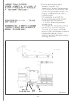
Page 15: ... up and down and keep the gap of presser foot and D6cutter device within 1 0 2 0mm FIG 5 Please turn off the power switch during adjustment and the adjustment operations must be carried out by professional technical personnel In addition please prevent the cutting tools from cutting your fingers during adjustment D6裝置的調整 D6 DEVICE ADJUSTMENTS 警告 進行調整作業時 請關閉電源開關 請專業 技術人員操作 另外 進行作業時 注意避免裁料刀具割傷 手指 1ø...

Page 16: ...eft and right direction of the feed roller 1 loose screw Sm441 and hexagon socket head cap screw SM514 FIG 6 2 keep spring plate FD621 fixed adjust the hex socket head cap screw SM514 in left or right direction to make feed roller and fabric forward motion as right angles 3 fasten hexagon socket head cap screw SM514 and screw SM441 ...

Page 17: ... The occlusion degree of the movable knife FD112C and the fixed knife FD616 would be larger Turn toward the direction B the occlusion degree would be smaller Please adjust the occlusion to 1 0 2 0mm The occlusion when manufactured According to the sewing requirements turn the screw SK462 to adjust the occlusion gap of the movable knife and the fixed knife Suggest enlarging the gap when sewing the ...

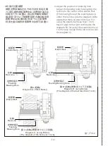
Page 18: ...two red lines For using the elastic belt less than 1 inch have it align to the right red line As the diagram B for using the elastic belt over 1 inch have it align to the left red line As the diagram C 圖 C 長輪 帶寬1英寸以上示意圖 Diagram C Long Roller The diagram of the belt over 1 inch 圖八 FIG 8 圖 A 短輪 Diagram A Short Roller 圖 B 長輪 帶寬1英寸以下示意圖 Diagram B Long Roller The diagram of the belt less than 1 inch 鬆緊...

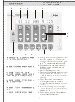
Page 19: ...indicates 0 5mm 65 indicates 6 5mm 5 Stitch setting Set the number of stitches that is required for each section The setting values are 0 999 stitches 6 Circulation setting It can memorize 10 sets of setting values of circulatory Sewing A J 7 Stitch count It counts the number of stitches that is completed 1 車縫模式指示燈 指示燈ON表示車縫模 式 指示燈OFF表示設定模式 2 準備鍵 可用於轉換車縫模式或設定模 式 3 工程段數 可設定1 18工程段數 4 送料長度 設定每針送料長度 ...

Page 20: ...arameter setting function 11 Manual key Turn on the switch manually to enter the next section 12 Automation key When the number of stitches is completed the system enters the next section automatically 13 Motor operating key Press this key to start the motor and the elastic tape can be fed or withdrawn P S parameter 9 setting value 0 When the motor operates the elastic tape is withdrawn parameter ...

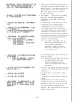
Page 21: ... trimmer delays cutting the thread The setting values are 0 800 0 indicates the time is 0 ms 800 indicates the time is 800 ms The accomplishment of the trimmer the needle numbers which need to sewing the rest elastic belt The setting value is 0 99 0 It indicates that the needful needle numbers is 0 99 It indicates that the needful needle numbers is 99 P S 1 If the setting value of the parameter 12...

Page 22: ... 0 1 0 It indicates that after feeding tape the back pedal would not execute the top bottom blow device 1 It indicates that after feeding tape the back pedal would execute the top bottom blow device 18 Set the number of stitches after which the function of gathering the lint through suction starting at the beginning of sewing ends The setting values are 0 99 0 indicates the number of stitches is 0...

Page 23: ...設定值5 80 5表示 當車縫結束後偵測到回踩踏板動作時 延 遲50ms才啟動送帶功能 80表示 當車縫結束後偵測到回踩踏板動作時 延遲800ms才啟動送帶功能 P S 當車頭伺服馬達設定車縫停止針棒停在下 停針位置 此時回踩踏板 伺服馬達會運 轉到上停針位置的設定狀態 為避免伺服 馬達運轉帶動檢知器而被系統誤判 並中 斷送帶動作造成送帶長度不準確 建議此 參數調整成25以上 視窗顯示 The panel shows Set the time of delaying the feeding function start The setting value is 5 80 5 indicate When the completion of sewing and the backward tread action is detected the feeding function will st...

Page 24: ...tting or end the Section canceling press the section selecting key 3 單一個段數設定 手動換段 3 Set the single section manual switch section 2 the setting ends press the cancel key section 2 tape feeding length 25 1 段數 Section 送帶長度 Tape feeding length 針數 Stitch 切刀 Trimmer 1 25 setting mode indicator light OFF 按工程選擇鍵 顯示工程2設定結束 顯示工程2送帶長度25 4 單一個段數設定 自動換段 4 Set the single section automatic switch 1 段數 Section 送帶...

Page 25: ...r automatically cut the thread and the number of Stitches automatically returns to zero 5 第一 二段設定自動換段 第三段設定手 動換段 5 Automatically switch to the first and the second sections manually switch to the Third section 3 2 1 段數 Section 送帶長度 Tape feeding length 針數 Stitch 切刀 Trimmer 1 25 100 2 3 35 40 100 ...

Page 26: ...he clothing and There are two kinds of section settings for both parts b The automatic trimming is adopted for the first elastic part and the manual trimming is adopted for the second elastic part section 1 2 3 automatic section switch section 4 Manual section switch 1 2 3 4 段數 Section 送帶長度 Tape feeding length 針數 Stitch 切刀 Trimmer 1 25 120 2 3 20 25 100 Auto 4 20 120 ...

Page 27: ...pulled back d 切刀動作完成後再車縫20針 啟動吸風集 塵與鬆線功能 d After the completion of the trimmer do 20 stitches then start the functions of the suction and loosing thread e 踏板回踩自動執行抬壓腳 並送入鬆緊 帶40mm e The pedal is lowered to automatically raise the presser foot and 40 millimeters of elastic tape is fed 5 CUT St 5 5 ...

Page 28: ...or Driver 電源供應器 Power Supplier 電源開關 Power Switch I O板 I O Panel 風扇 Fan 電磁閥 Solenoid Valve LED指示燈 LED Indicator 按鍵輸入區 Input Area 電源指示燈 Power Iight LCM顯示器 LCM Display 蜂鳴器 Buzzer LCM對比調整旋鈕 建議 將電阻值調整到中間 LCM Contrast Adjustment Knob Suggestion Adjust the resistance value to the middle value 操作板配置 Operation Board Position ...

Page 29: ...iver is no signal 檢查馬達FD674 連接線是否鬆脫 Check if the motor FD674 connection wire is loose 請重新連接後 再測試 Please reconnect and test 檢查電控箱內所有 連接線是否鬆脫 Check if there any connection wire in the electronic control box is loose 請重新連接後 再測試 Please reconnect and test 檢查送帶機構是否輕順 Check if the feeding achine is smooth and light 請確認調整送帶機構 Please check and adjust the feeding machine Yes Yes No No No Yes 檢查電源供應器FD677輸出電...

Page 30: ...alue to be A F For seaming on the heavy fabric set the output value bigger if the stepping motor driver is overheated adjust the value smaller A 9 8 0 F E D C B 1 2 3 4 5 6 7 RUN STOP Min Max 1 2 3 4 1P TEST OFF H 2P OFF ACD F 4 畫面顯示E01 The panel displays E01 表示安全開關被觸動 無法回復 It indicates that the safety lock switch is touched and cannot be reverted 畫面顯示E01 The panel displays E01 檢查送具是否 閉合在支架上 Check...

Page 31: ...更換新的I O板 FD678 Substitute a new I O oard FD678 更換新的檢知器 FD680 Substitute another new detector FD680 No No Yes Yes 無法排除E03 E03 cannot be solved 無法排除E03 E03 cannot be solved 更換後再重新測試 Substitute a new one and test 7 畫面顯示E04 The panel displays E04 表示圈數檢知器異常 無法正常動作 It indicates that the coil detector is abnormal and cannot work regularly The panel displays E04 檢查檢知器連接線 FD657 是否鬆脫 Check if the detector c...

Page 32: ...ontroller input function 先按住 切刀鍵 然後開機 即可進入系統輸入功能檢測 檢測內容 人機操作盒所有按鍵 1 安全開關 2 切刀開關 3 換段開關 4 回踩開關 畫面顯示 The panel shows Enter the input function in system to examine by keeping pressing trimmer key and then start the machine Examination All the keys on the machine box 1 safety lock switch 2 trimmer switch 3 section exchange switch and 4 back pedal switch C 控制系統回復出廠設定值 Revert the control system to the p...

Page 33: ... 29 ...

Page 34: ... 30 ...

Page 35: ... 31 ...

Page 36: ... 32 ...

Page 37: ... 33 ...

Page 38: ... 34 ...

Page 39: ... 35 桌板圖 TABLE CUT OUT OF 747S T5 ...

Page 40: ......

Page 41: ......

Page 42: ...LF D6 The specification and or appearances of the equipment described in this instruction book parts list are subject to change because of modification without previous notice FD696 AUG 2013 ...

Reviews: