


22
GB
1.0 - Items supplied
(Subject to technical changes)
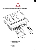
The control unit consists of the following components as supplied:
1. Control unit with operation panel and integrated load unit
2. Sensor with heater sensor and thermal fuse
3. Sensor with temperature sensor / humidity sensor
4. 2 sensor cases
5. 1 silicone sensor cable, 3/4-stranded, with an approx. length of 5 meters
6. Assembly bag (three 4 x 40 mm screws and four 3 x 30 mm screws)
2.0 - Technical data
Housing dimensions
Width 235 mm - height 195 mm - Depth 75 mm
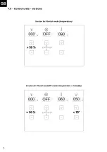
Operation
Touchpad – touch control
Display 4
sections of 15 mm x 30 mm each
Protection
IPX4
Rated voltage
400 V ~ 3 N PE
Switching power in Finnish mode
Maximum 10.8 kW ohmic load (AC1 operation)
Switching power in humidity mode
Maximum 9.3 kW plus 1.5 kW for the bio evaporator unit
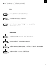
Control range for Finnish mode
5° to 100° Celsius - 5° adjustment
Control range for bio mode
5° to 70° Celsius - 5° adjustment units
Heater sensor limit
125° Celsius (heater sensor no. 1)
Temperature limit
140° Celsius (heater sensor no. 1)
Temperature indicator
Maximum 110° Celsius (RAL point sensor no. 2)
Humidity control
Measurement by humidity sensor – actual measurement
Heat cycle limit
240 minutes or 4 hours
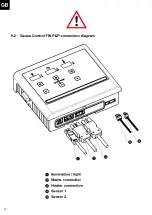
Lighting
Maximum 60 W – dimmable 10% adjustment units
Ambient temperatures
-15° to plus 40° Celsius
Ou tdoors
Protective enclosure required (splash proof)
3.0 - Explanation of symbols
Information!
This provides the user with useful information and tips about how to operate and use the
sauna system (sauna cabin, sauna heater and sauna controller)!
Warning!
Danger!
Warnings about possible dangers or dangerous situations which could even lead to loss of
life!
Caution!
Instructions or warnings which could lead to defects or damage to components if not ob-
served.
Electrical voltage!
Warns about voltage and high voltage! Failure to observe this warning may result in an elec-
tric shock.
Summary of Contents for Sauna 280
Page 1: ...Sauna 280...
Page 5: ...Sauna 280 1 4xM 4xM DET 1 2xDET A 1600 2100 mm mm DET 1...
Page 6: ...Sauna 280 2 I 1x DET 2 II 2 3a 3b 4 x DET 3a 4 x DET 3b 2x M X Z W Y 100 600 mm mm...
Page 7: ...Sauna 280 3 I II 16x M...
Page 8: ...Sauna 280 90 2x DET P 3A Bohren Sie 4 L cher in DET 2 10 mm...
Page 9: ...4 II I 3x I 3x I 4a 4b 4e 4f R ckwand Vorderwand R ckwand Vorderwand SAUNA 280...
Page 11: ...6 I II 11x DET 3b 10x DET 3a 8x DET 3a 8x DET 3b 16xH 16xH 20xH Siehe Seite 6A SAUNA 280...
Page 15: ...Sauna 280 9 2xDET F 1xDET G 1xDET F 3x K 3x K 3x K 3x K...
Page 16: ...Sauna 280 10 4x DET 7 12x H 575 I II 2xDET 8...
Page 17: ...Sauna 280 4xDET 9 4x H Bitte bohren Sie 4mm L cher vor dem festschrauben 4x H 11 4x H 770...
Page 21: ...Sauna 280 15 4x M 3x H 2xDET 19 2xDET 18 2x M 3x H...
Page 22: ...Sauna 280 16 I 10x H mm mm 2xDET 20 II 14xDET 21 28x H III Entfernen DET A...
Page 76: ...32...
Page 84: ...ISC GmbH Art Nr 086 50 009 23 11011 Stand 05 2020...
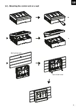
Page 90: ...6 D 6 0 Wandmontage Steuerger t 2 St ck Schrauben 4 x 25 mm 1 St ck Schraube 4 x 25 mm...
Page 91: ...7 D 7 0 Steuerger te Ausf hrungen 50 50 70...
Page 98: ...14 D Einstellung Beleuchtung 50 70 50 70 050...
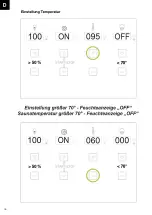
Page 100: ...16 D Einstellung Temperatur 50 70 50 70...
Page 101: ...17 D Einstellung Feuchte 50 70 50 70...
Page 102: ...18 D 50 70...
Page 117: ...33 GB Adjusting the lighting 50 70 50 70 050...
Page 136: ...52 50 70 50 70 050 F R glage de l clairage...
Page 155: ...71 50 70 50 70 050 I Regolazione dell illuminazione...
Page 159: ...75 50 70 I Se una funzione attiva il LED illuminato Il LED spento se una funzione non attiva...
Page 174: ...90 50 70 50 70 050 Regulaci n de la iluminaci n E...
Page 193: ...109 D 50 70 50 70 050 NL Instelling verlichting...
Page 212: ...128 50 70 50 70 050 CZ Nastaven osv tlen...
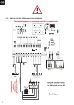
Page 221: ...137 D 13 1 St ckliste Sauna Control FIN Sauna Control FIN Artikelnummer 37 470 01 I Nr 18012...
Page 223: ...139 D 13 3 St ckliste Sauna Control BIO Sauna Control BIO Artikelnummer 37 470 11 I Nr 18012...
Page 232: ...148 CZ...
Page 238: ...154 D Stand 03 2019...