-
2
Danger
Immediate danger that can cause severe injury or even death.
몇
Warning
Possible hazardous situation that could lead to severe injury or
even death.
Caution
Possible hazardous situation that could lead to mild injury to per-
sons or damage to property.
The hot water generator HWE 4000 is a flow heater installed at
the factory for stationary high pressure cleaning units with blower
crash burner for heating oil "EL" or natural gas "H".
Note:
It is prohibited to use any other fuels!
The HWE 4000 is designed for three operating modes (also see
chapter "Function“):
–
Pressure-side hot water generation for stationary nozzle sys-
tems (for e.g. internal cleaners).
–
Generation of saturated steam for cleaning purposes (up-
grade kit for steam stage only).
–
Pressure-side hot water generation for operating the spray jet
with reduced flow quantity (upgrade kit for spray jet operation
only).
Note:
There is an important connection between temperature,
pressure and flow quantity in the 3 operating types. It is prohibited
to use components or attachments other than those listed in the
operating instructions.
This basically concerns:
–
All nozzles.
–
Pump module and attachments.
–
Burner and attachments.
Danger
Risk of injury! Follow the respective safety regulations when op-
erating at gas stations or other dangerous areas.
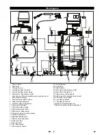
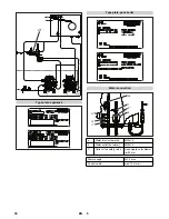
The plant drawing shows the appliance with a high pressure
pump module and all attachment sets connected in a series for a
specific purpose.
It is possible to operate in 3 modes through the physical relations
between pressure, flow quantity and temperature:
–
Operating with hot water
–
spray jet operation (with upgrade kit spray jet only)
–
Steam operation (with upgrade kit for steam stage only)
(see system schematic)
When you start the appliance, the pump module (1) transports
the entire flow quantity through the pass boiler (2) to the nozzles
(22) when the half load solenoid valve (16) is closed. The burner
ignites after approx. 30 seconds (both the stages). When the
maximum temperature is reached, the thermostat "hot water"
(10) switches off the second stage and switches it on again at
minimum temperature.
Features of this operating type:
–
Flow rate: maximum
–
Pressure: maximum
–
Temperature range: 70 °C to 95 °C
(see system schematic)
After starting, the pump module (1) transports a lesser quantity
(on account of smaller nozzle opening) through the pass boiler
(2) to the spray jet (23). After approx. 30 seconds, the stage 1 of
the burner is ignited. Stage 2 is blocked in this operating mode
through a signal from the switching head (9). Hence, the warming
up phase is a little longer. If there is constant use, the tempera-
ture also levels up at a constant value (physical balance).
Features of this operating type:
–
Flow rate: minimum
–
Pressure: maximum
–
Temperature range: below 100 °C
(see system schematic)
After successful starting, the pump (1) transports 50% of the flow
rate when the half-load solenoid valve (16) is opened; 50% flows
back in a pressure-less state back into the swimmer tank through
the pass boiler (2) to the steam nozzle (24). The burner ignites
after approx. 30 seconds (both the stages). When the maximum
temperature is reached, the thermostat "steam stage" (11)
switches off the second stage and switches it on again at mini-
mum temperature.
The size of the steam nozzle is designed in such a way that the
steam jet lies between 1.2 MP and 2 MPa. This helps in fulfilling
2 important conditions:
–
HWE 4000 is a fired pressure device of category III.
–
No steam is generated in the piping system.
Features of this operating type:
–
Flow rate: 50%
–
Pressure: minimum
–
Temperature range: 135 °C to 145 °C
Symbols in the operating instructions
Proper use
Please do not let mineral oil contaminated waste water reach
soil, water or the sewage system. Perform engine cleaning and
bottom cleaning therefore only on specified places with an oil
trap.
Function
Operating with hot water
spray jet operation (with upgrade kit spray jet only)
Steam operation (with upgrade kit for steam stage on-
ly)
27
EN
Summary of Contents for HWE 4000
Page 2: ...2 ...
Page 12: ... 10 Maßblatt c Brennkammer ausziehen d Kesselmantel abnehmen 12 DE ...
Page 35: ... 10 Specifications sheet C Pull out the burner chamber d Remove the boiler sleeve 35 EN ...
Page 59: ... 11 Feuille de mesure c Sortir la chambre de brûleur d Enlever le manteau de chaudière 59 FR ...
Page 107: ... 10 Måttblad c Dra ut brännkammare d Ta av behållarens mantel 107 SV ...
Page 131: ... 11 Φύλλο διαστάσεων c Εξαγωγή θαλάμου καύσης d Αφαίρεση μανδύα λέβητα 131 EL ...
Page 155: ... 10 Méret lap c Égéskamrát kihúzni d Kazánburkolatot levenni 155 HU ...
Page 178: ... 10 Přehled rozměrů c Vytažení spalovací komory d Sejmutí pláště kotle 178 CS ...
Page 202: ... 11 Arkusz z wymiarami c Wyjąć komorę spalania d Zdemontować płaszcz kotła 202 PL ...
Page 226: ... 11 Информационный листок с Извлечь топку d Снять обшивку котла 226 RU ...
Page 241: ......


