background image

– 4

The safety valve opens when the permissi-
ble operating pressure is exceeded (see 
Technical Data); water flows outside.
The safety valve is set by the manufacturer 
and sealed. Setting only by customer ser-
vice.

The thermostat valve protects the high-
pressure pump from unacceptable heating 
during circuit operation when the trigger 
gun is closed.
The thermostat valve opens when the per-
missible water temperature of 80°C is ex-
ceeded and lets out the hot water into the 
open.

DANGER

Risk of injury! Device, tubes, high pressure 
hose and connections must be in faultless 
condition. If they are not in a perfect state 
then the appliance must not be used.

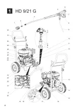
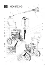
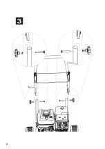
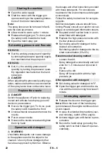
Figure 3, see cover page

Fasten the push handle by means of 
the fastening screws.

Note:

 The EASY!Lock system joins com-

ponents with a quick-fasten thread solidly 
and securely with just one turn.

Insert the high pressure nozzle onto the 
spray lance.

Install union nut and hand-tighten it 
(EASY!Lock).

Join the spray lance with the trigger gun 
and tighten until hand-tight 
(EASY!Lock).

Tighten the screw connection of the 
spray lance finger tight.

Join the high-pressure hose with trigger 
gun and high-pressure connection of 
the appliance and tighten until hand-
tight (EASY!Lock).

Check oil level of the high pressure 
pump at the oil sight glass. 

Do not operate the device if the oil level has 
fallen below the middle of the oil sight 
glass.

Add oil if required (see technical speci-
fications). 

Before using for the first time, cut off the 
tip of the lid of the oil tank on the water 
pump. 

Follow the instructions given in the sec-
tion "Safety Notes"!

Read the operating instructions of the en-
gine manufacturer before start-up and fol-
low the safety instructions carefully. 

Check oil level of the engine. 
Do not operate the appliance if the oil 
level has fallen below "MIN". 

If required, top up oil carefully.

Fill the fuel tank with unleaded petrol. 
Do not use 2-speed mixture. 
E10 fuel may be used.

Safety valve

Thermostat valve

Start up

Installing the pushing handle

Install hand spray gun, spray lance 

and nozzle

2.

1.

Check oil level of the high pressure 

pump

Motor

20

EN

Summary of Contents for HD 9/21 G

Page 1: ...HD 9 21 G HD 9 23 G 001 59672320 10 16 English...

Page 2: ...2...

Page 3: ...3...

Page 4: ...4...

Page 5: ...ituation which can lead to property damage 1 Nozzle screws 2 Nozzle 3 Spray lance EASY Lock 4 Pressure quantity regulation 5 Trigger gun EASY Force 6 Safety catch 7 Trigger 8 Safety lever 9 High press...

Page 6: ...separator according to EN 12729 type BA must be used Water that was flowing through a system separator is considered non drinkable High pressure cleaner to clean Machines Vehicles Structures Tools Fac...

Page 7: ...is no cover over the suction support Do not make any adjustments to the regulator springs regulator bars or oth er parts that can bring forth an increase in the engine speed Risk of burns Do not touc...

Page 8: ...the spray lance with the trigger gun and tighten until hand tight EASY Lock Tighten the screw connection of the spray lance finger tight Join the high pressure hose with trigger gun and high pressure...

Page 9: ...ppliance and let it run until the water exiting from the spray pipe is bubble free Switch off the appliance and fit the noz zle again DANGER Risk of explosion Do not spray flammable liquids DANGER Ris...

Page 10: ...ructions provided with these detergents For considerate treatment of the environment use detergent economically Follow the safety instructions for using de tergents K rcher detergents ensure smooth fu...

Page 11: ...ON Risk of damage Freezing water in the ap pliance can destroy parts of the appliance In the winter preferably store the device in a heated room If storing it in unheated rooms follow these instructio...

Page 12: ...o technical specifica tions DANGER Risk of injury if the machine is left running in an unattended state Before working on the device turn the start er to 0 OFF and remove the spark plug connector Risk...

Page 13: ...pair potential fail ures of your accessory within the warranty period free of charge provided that such failure is caused by faulty material or de fects in fabrication In the event of a warran ty clai...

Page 14: ...se to be valid if the machine is modified without our prior approval The undersigned act on behalf and under the power of attorney of the company man agement Authorised Documentation Representative S...

Page 15: ...height from open container m 1 Pump Working pressure MPa bar 4 21 40 210 4 23 40 230 Flow rate l h l min 250 850 4 1 14 2 530 930 8 8 15 5 Nozzle size high pressure 048 048 Nozzle size low pressure 25...

Page 16: ...2 1 2 3 EASY Lock 4 5 EASY Force 6 7 8 9 EASY Lock 10 11 12 13 14 15 16 17 18 19 20 21 22 23 24 25 26 27 EASY Lock 28 29 30 31 32 A B C D HD 9 21 G 1 HD 9 23 G 2 156 RU...

Page 17: ...3 K RCHER EN 12729 BA pH 6 5 9 5 120 0 5 mg l 50 mg l 20 mg l 300 mg l 240 mg l 200 mg l 28 dH 50 TH 500 ppm mg CaCO3 l 0 5 mg l 0 05 mg l 2 mg l 0 3 mg l 2000 1 30 157 RU...

Page 18: ...4 2 158 RU...

Page 19: ...5 80 C 3 EASY Lock EASY Lock EASY Lock EASY Lock MIN 2 1 159 RU...

Page 20: ...6 E10 7 5 3 4 3 4 0 160 RU...

Page 21: ...7 1 K rcher HD 9 21 G HD 9 23 G 161 RU...

Page 22: ...8 K rcher 0 6 1 5 0 1 2 3 0 OFF 162 RU...

Page 23: ...9 1 0 OFF 500 163 RU...

Page 24: ...10 1 0 OFF 3 164 RU...

Page 25: ...11 www kaercher com 2 637 002 0 2 637 007 0 Cage 30190 3 0 1 9 0 30190 09 2 013 165 RU...

Page 26: ...Winnenden Germany 49 7195 14 0 49 7195 14 2212 Winnenden 2015 12 01 U HD 9 21 G 1 810 xxx U 2006 42 EC 2009 127 EC 2000 14 2014 30 EU EN 60335 1 EN 60335 2 79 EN 55012 2007 A1 2009 2000 14 V dB A HD 9...

Page 27: ...1 3 5 0 9 0 9 15W40 6 288 050 0 IPX5 C 60 1000 16 7 1 10 7 5 3 4 1 4 21 40 210 4 23 40 230 250 850 4 1 14 2 530 930 8 8 15 5 048 048 250 250 l 27 270 27 270 C 80 0 35 15W40 6 288 050 0 0 50 0 0 8 48 5...

Reviews: