background image


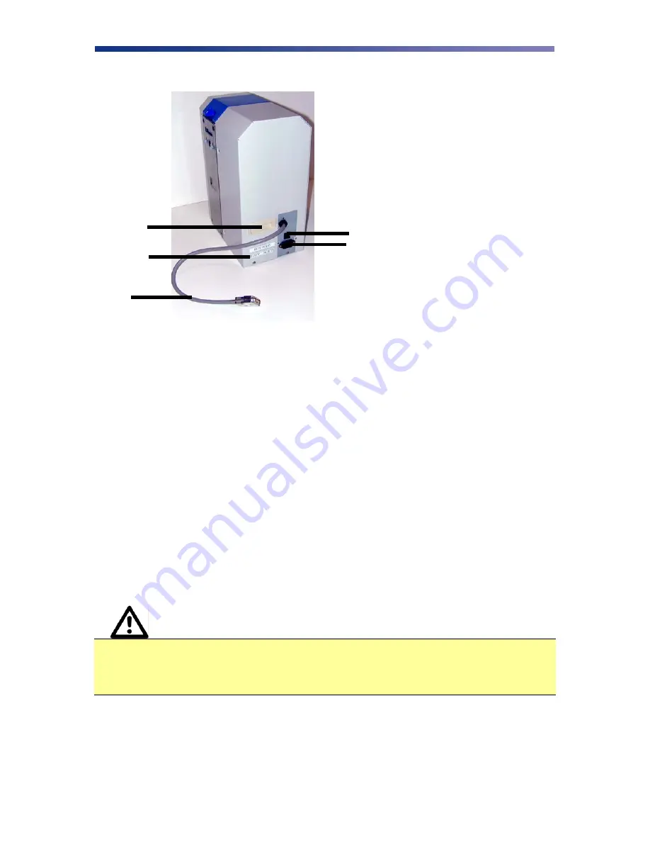
Rear of the Heat Roller Unit  


A. Circuit Breaker 


Protection device that stops current if there is a direct short or excessive heat


B. Power 

Receptacle 


 Supplies power to the Heat Roller Unit


C.  Printer Connecting Cable 


The cable used to connect the Heat Roller Unit to the printer.


D.  Power Rating Label 


Identifies the correct power source for the Heat Roller Unit. 

E.  

Handle 


Used to easily lift the Heat Roller Unit. 

Unpacking the Heat Roller Unit 

Follow these steps to unpack the Heat Roller Unit.  Be sure to select a location that meets the 
general requirements as stated above. 


Caution


IMPORTANT!  

The Heat Roller Unit must be placed on a level surface, in a 

dust free environment next to the PR5300.  It is essential to be able to access the 
Heat Roller Unit from all sides for its installation.  It is also recommended that 
you have one or more persons to assist with unpacking the Heat Roller Unit. 

1.  Place the shipping carton on a firm level surface.  While unpacking, inspect the carton to 

ensure no damage occurred during shipping. 

2.  Remove the Heat Roller Unit and accessory box from the packing box. 

A
B

C

D

Summary of Contents for TEAMNisca PR5302

Page 1: ...Somerset NJ 08873 Copyright 2004 Kanematsu USA All rights reserved TEAMNisca and the TEAMNisca logo are a registered trademark of Kanematsu USA Inc Microsoft and Windows are U S trademarks of Microso...

Page 2: ......

Page 3: ...t to the Printer 8 Loading the Laminate Ribbon 9 Turning on the Printer and Configuring Lamination Settings 11 Chapter 3 Using the Heat Roller Unit Configuring Heat Roller Preferences 14 Overlay and L...

Page 4: ...fferent types of laminate material Sensitive position adjustment settings to optimally locate the laminate on the card Provides a sleep mode to conserve energy About This User s Guide This User s Guid...

Page 5: ...nt debris from entering the Heat Roller Unit Do not place any heavy objects on the Heat Roller Unit Use only a power source indicated in the electrical requirements section Do not place the Heat Rolle...

Page 6: ...Unit could get wet Personal injury could result The Heat Roller Unit must be connected to a grounded electrical power supply and properly protected against electrical surges and grounding faults Phys...

Page 7: ...for lamination when leaving the printer B Printer Heat Roller Unit Attachment Allows the printer and Heat Roller Unit to attach together C Laminate Ribbon Supply Spool Used to load new laminate ribbo...

Page 8: ...sy access to the flip turn rollers Left Side of the Heat Roller Unit A Front Access Cover Opens to allow access to the laminate ribbon B Heat Lamp Panel Opens to allow access to the inside of the heat...

Page 9: ...hese steps to unpack the Heat Roller Unit Be sure to select a location that meets the general requirements as stated above Caution IMPORTANT The Heat Roller Unit must be placed on a level surface in a...

Page 10: ...tape 5 Remove all packing material from the heat lamp unit Note Keep all packing material in case you need to move or re ship the Heat Roller Unit Connecting the Heat Roller Unit to the Printer Cautio...

Page 11: ...Unit and the entire unit is level 4 Insert the cable from the Heat Roller Unit into the options port on the back of the printer Tighten the screws 5 Attach the card stacker into the mounting slots 6...

Page 12: ...eed the ribbon onto the take up roll Turn a couple of turns to load the laminate ribbon 3 Open the heat lamp panel by depressing the lever on the left 4 Open the front access cover and slide the lamin...

Page 13: ...variety of different settings based on various laminate ribbon When powering up the printer and Heat Roller Unit the printer automatically detects the Heat Roller Unit Before using the Heat Roller Un...

Page 14: ...y be selected by pressing the EXE button The available types are Hard Coat Type 1 This is used for clear 1 mil patch ribbon or holographic ribbon with 1 5 mil carrier Hard Coat Type 2 Used for hologra...

Page 15: ...travel speed settings need to be optimized The default settings are 0 for travel speed and 0 for heat Some common problems can be fixed by changing the travel speed and or laminator heat settings Pres...

Page 16: ...ences within the printer driver To open the PR5300 Printer Driver Printing Preferences refer to the following steps Windows 2000 Windows XP 1 Click on the Start button point to Settings and select pri...

Page 17: ...to reduce the risk of card jams caused by curled cards being pulled back into the printer Printing a Sample Card A sample application is included with the installation of the printer driver To print...

Page 18: ...able options and make any necessary changes Note Whenever laminating with hard coat type laminate the setting for clear overlay on the front and back side must be set to Do Not Apply to ensure proper...

Page 19: ...n IMPORTANT The surface of the heat rollers can exceed 150 C when in operation Turn the power OFF and let the heat rollers cool for at least 30 minutes before cleaning Basic Automated Cleaning A basic...

Page 20: ...access the User Mode menus 3 Press the Menu button to navigate to the Cleaning sub menu 4 Open the card feeder door on the printer and remove any blank cards 5 Remove the protective paper backing fro...

Page 21: ...cleaning procedures should be performed to remove dust and other contaminants Cleaning the Platen and Capstan Rollers 1 Power OFF the printer Heat Roller Unit and remove the power cord 2 Remove the 4...

Page 22: ...he Heat Roller Unit by depressing the release button 3 Open the flip turn cover and manually rotate the flip turn transport roller 180 by moving the unit counter clockwise 4 With the front access cove...

Page 23: ...lear button for more than 3 seconds while the Printer Heat Roller Unit performs a soft reset Interpreting General LCD Messages LCD SCREEN MESSAGE PROBABLE CAUSE ACTION H Roller Cover is Open The front...

Page 24: ...eat rollers can exceed 150 C when in operation When clearing a jam turn the power OFF and let the heat rollers cool for at least 30 minutes LCD SCREEN MESSAGE PROBABLE CAUSE ACTION Card Jam HR Unit Ar...

Page 25: ...the power switch on the printer Verify the ROM version of the heat roller is ExH Roller 1 0 in the User Mode ROM menu Ensure the Heat Roller Unit cable is securely connected to the back of the printer...

Page 26: ...al Count Printer Ribbon Ribbon Selection Heat Speed Front Values from 5 5 Image Setup H Roller1 Ribbon Laminate Ribbon Selection Heat Temperature Values from 5 5 Error Buzzer On Off Heat Adjustment1 R...

Page 27: ...m PVC Medium size CR 80 54x86mm Print area Entire card surface Printing speed 30 seconds maximum Transfer laminate TEAMNisca protective holographic ribbon Communication RS422 printer to heat roller Po...

Reviews: