33
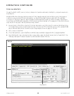
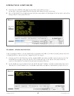
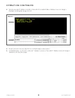
OODMANUAL 0720
KAM CONTROLS, INC.
If experiencing any of the issues listed below, please proceed to follow instructions on each of the following sections
in their specific order, starting with the "Power Verification" section.
•
Instrument is not powering on
•
No 4-20 mA Output
•
PLC is not reading the 4-20 mA Output
•
No RS232 communication
•
No RS485 communication
•
Output is not changing
•
Instrument does not calibrate.
To perform any of the troubleshooting procedures, you will need to access the boards. To do so, use a 7/16" wrench to
remove the (6) hex screws on the electronics enclosure and remove the cover.
A device to measure both voltage and amperage is needed during the troubleshooting process. Please have a
multimeter available before proceeding.
NOTE: Regardless of the problem being experienced, the troubleshooting steps need to be followed in order, starting
from the "Power Verification" section.
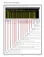
POWER VERIFICATION
6 T R O U B L E S H O O T I N G
LED2
5VDC
TP5
TP2
GND
TP4
TP1
3939 ANN ARBOR DRIVE
HOUSTON TX - 77063
Tel. +1-713-784-0000
Fax: + 1-713-784-0001
www.Kam.com
KAM OOD
MADE IN USA
RS232 RXD
CHS GND
RS232 TXD
GND
POWER (+)
POWER (-)
485 RX
485 TX
DIGITAL OUT
CHS GND
4-20 mA (+)
4-20 mA (-)
TP3
LED1
LED1
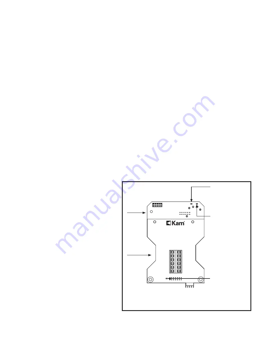
LED 1 on the
Processor Board
indicates
voltage presence
at the 5 V supply
LED 2 on the
Processor board
indicates
voltage presence
at the 3.3 V supply
LED1 on the
Terminal Board
indicates
voltage presence
at the input
voltage terminals
1.
Use a multimeter in voltmeter mode to
measure the voltage across the power
loop terminals POWER (+) and POWER (-).
The voltage should be within the
instrument’s requirements (12 V to 24 V)
and close to the power supply ratings
(+/- 0.5 V). For example, a 24 V power
supply could measure 23.5 V on the OOD
terminals. If the voltage is not within those
requirements, verify that the power supply
has a wattage capability of 5 Watts, and
check for any blown fuses, faulty wiring,
or a faulty power supply. If LED1 on the
Terminal Board does not light up, but the
voltage at the power terminals is within
the appropriate range, it indicates a bad
LED. The faulty LED will not affect the
operation of the instrument, since it is only
an indicator that a voltage is present.
2.
Once voltage across power loop terminals
has been verified, make sure the OOD
is wired with the correct polarity as per
the wiring diagram on page 14 of this
manual. If the polarity is wrong, turn off
the power and rewire the OOD with the
correct polarity. Turn the power back on
when done.
FIG. 6-1
There are 3 LEDs on the OOD electronics (two on the Processor Board and one on the Terminal Board). These LEDs
indicate the presence of power. When any of the LEDs are lit, it indicates that there is voltage going to the boards,
but not necessarily the proper voltage. When any of the LEDs are not lit, it may indicate they are damaged. In any
case, the first step is to check all power supplies. Please follow the procedure below.
NOTE: The OOD has built-in protection to avoid incorrectly
polarized voltages from damaging the instrument.
Processor
Board
Terminal
Board

