83
2. DVR Installation
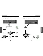
3.RX Receiver Connection Diagram
RX
Recei
ver
Connect
ion
Diagram
82
2. DVR Installation
RX
Recei
ver
Connect
ion
Diagram
83
82
3.1 Part Name and Description
1.
Turns “ON” when polarity of data lines connected correctly.
2.
Used for ON-OFF of the cross resistance according to the international standard, EIA-485.
3.
DC±6V when it is LOW, DC
±
12V when it is HIGH.
4.
Used for reversing the polarity of ZOOM/FOCUS control output.
5.
Used along side with MATRIX CARD, else it is "0"
6.
Turns “ON” when summoned camera number from DVR or TX match.
7.
Created from the left in order of “100/10/1”
8.
Output of EXT is adjustable from DVR depending on the condition at site.
9.
P/T control voltage output is classified into AC24V and input voltage. The default is AC24V.
10.
Input voltage selection switch for AC 110V/220V. The default is AC220V.
11.
High end commercial usage only, PIC 16F74
12.
Can be replaced with National N75176-Japan or Maxim MAX485 IC-USA.
13.
Used to check the condition of PAN/TILT and ON-OFF output.
14.
Used to check the condition of MOTORIZED ZOOM LENS output.
15.
Input power is 250V/10A when AC 110V is selected, and is 250V/5A when AC220V is
selected.
16.
Main power switch capable of ON-OFF on 2 lines at the same time.
17.
Data input terminal capable of receiving RS-485EIA signal; be cautious of polarity.
18.
3 lines per output, in order of ZOOM(1)/FOCUS(2)/COMMON(3)
19.
Arranged in order of UP/DOWN/LEFT/RIGHT/AUTO PAN/COMMON (4,5,6,7,8,9
consecutive)
20.
Power output related to camera and its housing; AC voltage output.
21.
LIGHT/AUX 1,2/AUDIO - Maximum of 1KW of AC voltage output
22.
AC power source used for installation/repair, usable by connecting to wall outlet.
23.
Used in main power input terminal of AC 110V, or alternate power of 220V.
[Caution]
The voltage of the light controlling output port is the same as the AC input
voltage. The operating voltage of the camera lens is fixed to DC 12V.
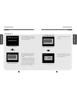
3. RX Receiver (KRE-303) Connection Diagram (optional)
RX-RECEIVER Internal View
3.RX Receiver Connection Diagram

