background image

19

1. Guide

5. Search

S

earch

18

1. Guide

S

earch

5. Search

5.1 Accessing Search Mode 

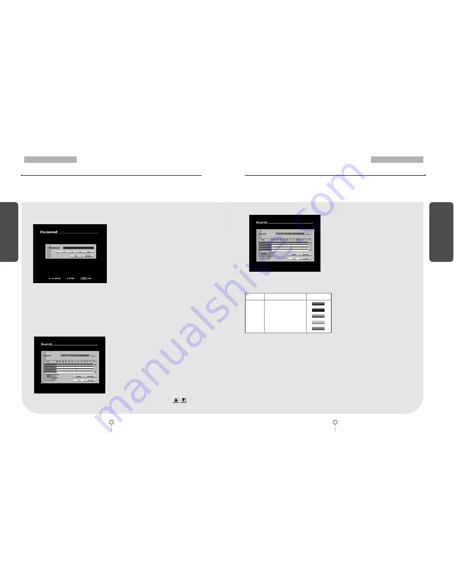
[Figure 5-1. Password screen]

[Figure 5-2. Search mode display]

To access Search mode, press Search button on the system. You will then be asked to enter
password as shown below :

After you enter the correct password, the
Search mode display will appear as shown
below. You can select from the different
options by using the mouse or the
[directional] keys.

Use the [number] keys to enter the correct 4-
digit password, then press [Enter] (The system
has no password under factory settings).

If you forget your password, you will not be
able to access Search mode, or change your
password. We strongly recommend that you
either write down your password and keep it
safe or use a password that you are sure to
remember. (See page 34 for instructions on
how to change password). 

To return to Surveillance mode, press [Search]
button at anytime. 

[Figure 5-3. Graph color display]

[Table 5-1. Graph color description]

Recorded data shown on the time graph will

be displayed in different colour depending on

the recording type enabled (see Table 5-1

below).

In Search mode display, you can select the
time and date and the camera channels you
wish to view.

To choose the date you wish to view, select the
[Date] button. This will display a calendar.
From there, select the day you wish to view
(see pages 20 for details).

The recording for each camera will be
displayed in the time graph. 

If a camera is connected to an Audio input, the
system will replay both video and audio at the
same time.

After selecting the time, date and camera
number, press [OK] button to view the
recording.

When the system is replaying the recording,
you can enlarge any channel into full screen
mode (see page 23 for details). 

Press the [Up] and [Down] (            ) arrow
button to select any channel to search.                    

5.2 Search mode display 

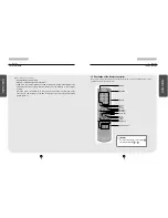
5.2.1 Graph color display

Color

Description

Display

• Purple

Continous Recording

• Blue

Motion-detection Recording

• Green

Pre-alarm Recording

• Orange

Sensor Recording

• Red

Audio Recording

Summary of Contents for DW-709

Page 1: ...ins information on DW 709 716 which will enable you to use this product properly If you require additional copies of this manual please print the manual contained in the CD provided with your purchase...

Page 2: ...d by strict reliability and compatibility testing This DW 709 716 manual provides necessary information for the correct use of this product and also contains some useful tips Please read this manual t...

Page 3: ...ctive owners The following words and symbols mark special messages throughout this guide WARNING Text set off in this manner indicates that failure to follow directions could result in bodily harm or...

Page 4: ...ave obtained then you must have a reasonable mechanism in place to ensure that your use of the SOFTWARE does not exceed the use limits specified for the license you have obtained This license authoriz...

Page 5: ...may result in Kaltech Enterprises s inability to provide the End User with updates to the SOFTWARE and the End User assumes the entire risk of performance and result in such en event c VOLUME USE If t...

Page 6: ...ENT SHALL KALTECH ENTERPRISES BE LIABLE TO THE END USER EXCEPT IN RESPECT OF DEATH DAMAGE TO PROPERTY OR PERSONAL INJURY CAUSED BY KALTECH ENTERPRISES S FRAUD OR GROSS NEGLIGENCE FOR AN AMOUNT IN EXCE...

Page 7: ...F OR IN CONNECTION WITH ANY ACT OR OMISSION OF KALTECH ENTERPRISES RELATING TO THE USE OR INABILITY TO USE THE PRODUCT BY THE END USER 11 NO LIABILITY FOR DAMAGES INCLUDING WITHOUT LIMITATION CONSEQUE...

Page 8: ...at sources such as radiators Heat registers stoves or other product that produce heat 5 Water and Moisture Do not use this product near water Do not exceed the humidity specifications for the product...

Page 9: ...Surge Protection A UPS is mandatory for efficient functioning of your Digital Watchdog unit When shipping the DW Pro unit the original shipping carton packing materials come in handy For maximum prot...

Page 10: ...res which result from accident misuse abuse neglect mishandling misapplication alteration modification faulty installation set up adjustments improper antenna inadequate signal pickup maladjustment of...

Page 11: ...g Search mode 18 5 2 Search mode display 18 5 2 1 Graph color display 19 5 3 Selecting date and time 20 5 3 1 Selecting date 20 C Co on nt te en nt ts s 5 3 2 Selecting cameras and changing graph bar...

Page 12: ...tching to Control Mode 75 Chapter 2 DVR Installation 1 Pan Tilt Connection 2 Connecting LAN PSTN Communication Lines 2 1 LAN ISDN with the Router and Dedicated Line Connection 80 C Co on nt te en nt t...

Page 13: ...1 System Overview 2 Surveillance mode 3 Menu Operation 4 Pan Tilt Camera 5 Search 6 Backup 7 System Setup 8 Controls Manual Control 1 Guide...

Page 14: ...o Control setup mode from the Surveillance mode Jog inner dial Rotate to view recordings in Search mode forwards or backwards one frame at a time Rotate to change the value of options one unit at a ti...

Page 15: ...image Removable Disk support POWER LED When power switch is on the LED gives green light Power Connector Power cable input 110V 220V for system main power Supply Camera Video Input BNC 16 BNCs for DW...

Page 16: ...ut Replay of recorded Audio External modem terminal NOT AVAILABLE IN EUROPEAN MODELS Provide a connection to the external modem for a remote access LAN Ethernet 10 100 connection port for connecting t...

Page 17: ...UTO Dot Delete Shuttle Shuttle Arrow key Enter Jog Jog Playback Screen division IMAGE I NPUT OUTPUT SWITCH Image Input Output terminal options NTSC PAL Default settings for input video format CVBS VGA...

Page 18: ...tatus Shows audio recording enabled 2 3 4 5 1 2 Surveillance Mode 1 1 2 Surveillance Mode Survei l l ance Mode To Select Full Screen mode Press any key 1 16 on the system to enlarge that camera channe...

Page 19: ...clicking the icon by mouse or pressing the front panel key Figure 3 1 Pop up menu operated by mouse on surveillance mode Notice Right mouse click Click right mouse button to activate or deactivate pop...

Page 20: ...igure 4 1 Enlarged P T Z channel Figure 4 2 P T Z control mode 3 3 Using menu on playback mode Click this button to select time and date to search Click this button to start backup Refer to page 24 fo...

Page 21: ...P T Mode To set the position of the Speed Dome camera to Preset buttons change the Cursor Mode to P T Mode then move the camera position using the directional keys Once the camera is in the designed...

Page 22: ...re 5 3 Graph color display Table 5 1 Graph color description Recorded data shown on the time graph will be displayed in different colour depending on the recording type enabled see Table 5 1 below In...

Page 23: ...ish to view press the OK button to return to Search mode display The system will display the selected date s recording in the time graph Selecting cameras Use the mouse or the directional keys to sele...

Page 24: ...playback use the number keys 1 16 on the system to select the channel you wish to enlarge When a channel is selected use zoom in zoom out keys to increase or decrease the screen size Changing playback...

Page 25: ...will return to Search mode display Once backup is complete the system will return to Search mode display Backup mode Video To select KDB Kaltech data base or AVI backup mode use the mouse or the dire...

Page 26: ...USB drive Figure 6 7 Selecting Local Drive Note Supported USB versions DW 709 716 supports USB 1 1 USB 2 0 devices are also supported but at USB 1 1 speed Recommended portable USB Hard Disk Drives in...

Page 27: ...e recording you wish to save When saving backup in KDB format you can select multiple camera channels When saving backup in AVI format you can only select one camera channel When saving backup in Vide...

Page 28: ...nect Disconnect or Connect fail message Figure 6 16 Remote drive setup 6 3 Printing Still Image Figure 6 17 Search Backup DW 716 Figure 6 18 Local Printer Selection Save image Select BMP or JPEG to pr...

Page 29: ...ite code date display type and time System Software Upgrade Update system program Setup Log Information Show recorded log information OSD Dwell Time Turn OSD on off and set automatic channel rotation...

Page 30: ...on Figure 7 6 Site Information setup In Site Information you can change the Site Code Date Type and Time Setup options Language Select the language you wish to use Site Code You can assign an ID code...

Page 31: ...hen use the mouse wheel or the jog shuttle to change the option If Daylight Saving applies in your region select the Daylight Saving option 7 3 3 Software Upgrade Figure 7 10 Software Upgrade Figure 7...

Page 32: ...ded on different date time Change Start Time and End Time using the mouse and mouse wheel or the directional keys and the jog shuttle then press OK button The system will display the log information r...

Page 33: ...Information Network connection history Figure 7 18 Log Information Backup history Figure 7 19 Exiting Log Information menu 7 3 5 OSD Dwell Time Figure 7 20 OSD Dwell Time Figure 7 21 OSD Dwell Time s...

Page 34: ...ou wish choose press OK button Select Network Management to check the network status or to restart DDNS authentication and click OK button Assigned IP Assigned IP displays the system s IP address used...

Page 35: ...tion and click the OK button Authentication Number Enter the DDNS authentication number I D Enter DDNS ID Password Enter DDNS password Select Options to set a warning beep in case of video loss or to...

Page 36: ...t the video input type of the image source Figure 7 32 Selecting HDD Management Figure 7 33 HDD table To renew the HDD installed in the system select HDD Management and click the OK button The table s...

Page 37: ...le select Cancel button You can view the HDD format progress through the progress bar The system will restart once the format is complete Figure 7 34 Confirmation message Figure 7 35 HDD format progra...

Page 38: ...ne while the NTP feature is enabled The NTP server and the system are synchronized every hour IIS SO O A Ar re ea a N NT TP P S Se er rv ve er r A Ad dd dr re es ss s Worldwide pool ntp org Asia asia...

Page 39: ...start Restart the system Add schedule Add automatic reboot schedule see page 53 for details Note Press and hold ENTER button at the front panel for 3 seconds to restart the system Add schedule You can...

Page 40: ...n the system to select other cameras for set up 7 4 2 Motion Detection Figure 7 43 Motion Detection Figure 7 44 Motion detection setting In Motion Detection menu you can set motion detection area set...

Page 41: ...he mouse wheel or the jog shuttle to change the recording mode Available recording modes are listed on the table below You can also set non recording period per camera if you wish to Apply All Click t...

Page 42: ...ish to change its options on P T Z model type sensor settings sensor control link settings sensor camera link settings and camera name Use the mouse wheel or the jog shuttle on the system to select a...

Page 43: ...setting Figure 7 55 Sensor setting In Sensor setting menu you can select a sensor type for any of 4 connected sensors and enable or disable alarm sound Sensor Use the mouse wheel or the jog shuttle t...

Page 44: ...nged in 10 seconds segments up to maximum of 300 seconds Use the mouse wheel or the jog shuttle to change Control Time 7 5 4 Sensor Camera Link Figure 7 58 Sensor Camera Link Figure 7 59 Sensor camera...

Page 45: ...r through modem see page 67 for details Not in Europe Transfer Time Transfer Time determines how long the system will transfer the recording to the computer with the Center software installed when con...

Page 46: ...nter PC Use the mouse or the directional keys to enter IP address Center IP address setup When using LAN you must enter the IP address of the computer installed with the Center Program Use the mouse o...

Page 47: ...storage device set by the schedule You can only schedule the system to save a backup copy of the recording that will be recorded in the future You cannot schedule the system to save a backup that has...

Page 48: ...ave a remote drive backup by entering the correct IP address When saving a remote drive backup the receiving PC or fileserver must have the Center Program installed with Backup Server Program running...

Page 49: ...or Connect fail message OK Once you have entered the Network Drive IP Network Password and Network Drive Path select OK button to return to Backup Schedule list Rotate You can schedule the system to...

Page 50: ...and return to Setup menu If you wish to use the control devices manually select the 16 splitscreen mode in Surveillance mode then press Enter key You will then be able to select the control devices y...

Page 51: ...nection 2 Connecting LAN PSTN Communication Lines 3 RX Receiver KRE 303 Connection Diagram optional 4 External Sensor Connection Input 5 Control Port Connection Output 6 Adding HDD 7 HDD Smart Check 2...

Page 52: ...Signal Cable Connection Port Used for connecting RX Receiver Caution Please beware of ve and ve poles of the signal cable when connecting A Wrong connection may cause malfunction to the system If you...

Page 53: ...ction options Not available Europe 2 1 LAN and Dedicated Line Connection Dedicated Line Internet Network Local Internet Network PSTN Telephone line DSU Dedicated Modem DSU Dedicated Modem Router Cente...

Page 54: ...l N75176 Japan or Maxim MAX485 IC USA 1 3 Used to check the condition of PAN TILT and ON OFF output 1 4 Used to check the condition of MOTORIZED ZOOM LENS output 1 5 Input power is 250V 10A when AC 11...

Page 55: ...e 59 for details on Sensor type setting 5 Control Port Connection Output Alarm Light Amplification Siren External Relay Etc External Power DC12V Caution The operating voltage should be maximum 12V 300...

Page 56: ...elect OK button The system will display a confirmation message shown in Figure 6 4 Select Cancel buttontoexitHDDtablescreen All Format Press All Format button to format all existing HDDs The system wi...

Page 57: ...from bad sector or overheating HDD warning icon WhentheinstalledHDDhasaproblemsuchasbadsectororoverheatedDVRwillbeeporthisicon willappear ItisstronglyrecommendedtoreplaceHDDwhentheHDDwarningicon appe...

Page 58: ...CD containing KDB Kaltech Data Base data in CD RW it will start by autorun If you do not have autorun on your PC you can access the viewer file by double clicking the Viewer folder The Viewer will wo...

Page 59: ...number of cameras you choose in a form of 4 9 or 16 DW 716 split screen SKIP Move the slides to the right if you wish to increase search speed The number of images to be skipped are set by an interna...

Page 60: ...Embedded Linux LAN Ethernet 10 100 MB Modem 56Kbps External type modem is supported Optional but not available in Europe Video Input 9Ch DW 709 or 16Ch DW 716 Composite Video NTSC PAL Video Output Gen...

Page 61: ...not displayed Check if the camera video output is connected to DW 709 716 DVR system correctly Check if the power cable on the camera is connected correctly Check if the video cable connecting the cam...

Page 62: ...t t W Wa ar rr ra an nt ty y ver 1 0 0408 E 9 8 3 Appendix 3 FAQ FAQ Color of some camera videos are strange or videos are shown abnormally Check if the camera connected to the system has a problem Ch...

Reviews: