~ 9 ~
4.1.3 Flue gas extraction
GENERAL
Flue gas extraction is an essential part of your heating installation. Well-assembled flue gas extraction
considerably extends the working life of your heating boiler and has a positive effect on heating efficiency.
Warning:
Because in most cases the flue gas temperature is higher than 180 °C, it is the
desirable to insulate the outlet with heat-resistant material in places where
contact with body parts is possible. These are available from Kabola Heating
Systems B.V.
Ensure the correct length/diameter proportions. We advise assembling a flue gas outlet with a
diameter of 60 mm with a maximum length of 5 meters.
On sailing and seagoing vessels we advise using a vertical flue gas discharge system (see fig 5).
AUTOMOTIVE APPLICATION
With the installation of the heating system for an application not for use on water, one can decide to
keep the flue gas outlet as short as possible.
HORIZONTAL OUTLET WITH SKIN FITTING
It is possible to bring the flue gas outlet horizontally from the boiler through the wall. The following
points must then be respected:
The maximum permitted length without bends is 3 meters.
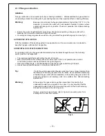
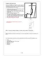
Make sure that the outlet is amply above the water level. If this is not possible use a curved
construction (a swan neck as pictured on the right in figure 4).
Use a skin fitting (single- or double-walled) to bring the flue gas outlet through the wall.
Use as few as possible bends, no more than 3 bends of 90 °.
Tip:
If with the existing assembled flue gas outlet you have a larger diameter than
the diameter of the flue gas outlet from the boiler, we recommend assembling
a flexible flue gas outlet (50 mm diameter) in the existing flue gas outlet. The
necessary adaptors and auxiliary parts are available from Kabola Heating
Systems B.V.
Warning:
When using a flue gas outlet longer than prescribed it is possible that
condensation water may originate in the outlet. It is very important that the
condensation water does not form a water trap with the flue duct becoming
blocked (as pictured on the left in figure 4).
Using a swan neck (as pictured right in figure 4) prevents water from
entering the flue duct from outside.
Fig. 4
Summary of Contents for HR Series
Page 1: ...1 Userguide HR HRE series Eng HRE CH HR CH HR Calorifier HR Combi...
Page 21: ...21...
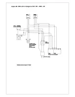
Page 22: ...Appendix B Electrical diagram 230V HR HRE CH...
Page 23: ...Appendix B Electrical diagram 230 V...
Page 25: ...Appendix E Burnerparts...
Page 27: ...Appendix G CE declaration HR 300 HR 500 HRE 300 HRE 400 HRE 500...


