


~ 7 ~
4 Installation and bringing into use
In this section you can find instruction and tips for the correct placing and connection of the
boiler and the associated equipment.
Warning:
Do not place any flammable and/or gaseous substances that may cause
danger of explosion or fire in the space where the boiler is or is to be
installed.
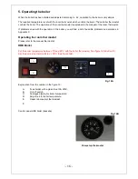
4.1
Installation
4.1.1 Placing the boiler
Place the boiler in a moisture-free space.
Place the boiler on a strong, horizontal surface and fasten it firmly with the angle brackets and
M5 bolts supplied.
Ensure sufficient ventilation in the space where the boiler is to be installed.
As a general rule for determining the diameter of the ventilation opening you can use 2.5 times
the diameter of the flue gas outlet (at least 150 mm).
Secure the base of the boiler against slipping using an angle bracket with bolts or tack-
welding.
Make sure there is a distance between the outlet and the wall of at least 10-20 mm because of the
heat transfer from the flue gas outlet.
Ensure sufficient space around the boiler for service and maintenance work.
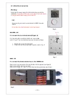
Provide an earthed wall socket (230 V AC) for the connection of the boiler.
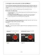
4.1.2 Connection to the central heating system
PIPING
When assembling the piping the following points must be respected:
Assemble the piping in such a way that the boiler and control panel remain accessible;
Ensure sufficient ventilation in places where air can accumulate.
Note:
Ensure ventilation if the piping does not slope upwards.
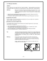
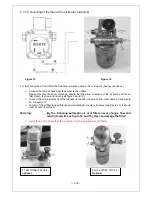
EXPANSION TANK
An expansion tank must always be assembled with a closed central heating system (pressure system).
Always assemble the expansion tank in the return pipe (see fig 2) as near as possible to the boiler.
The size of the expansion tank is approximately 10% of the total water capacity of the whole system.
For example; with a volume of 120 litres, assemble a 12-litre expansion
tank.
Summary of Contents for HR Series
Page 1: ...1 Userguide HR HRE series Eng HRE CH HR CH HR Calorifier HR Combi...
Page 21: ...21...
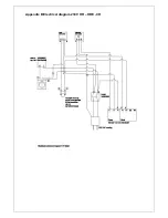
Page 22: ...Appendix B Electrical diagram 230V HR HRE CH...
Page 23: ...Appendix B Electrical diagram 230 V...
Page 25: ...Appendix E Burnerparts...
Page 27: ...Appendix G CE declaration HR 300 HR 500 HRE 300 HRE 400 HRE 500...


