background image

3

CDX-09 I

NSTALLATION

 I

NSTRUCTIONS

Please read all instructions carefully before you install and use your CDX-09 Lock 
Assembly. This will help you avoid unnecessary costs and concerns resulting from 
improper installation.
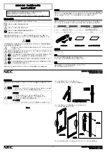
BASIC TOOLS NEEDED

1.  Medium Phillip’s screwdriver (#1/#2).
2.  Standard hacksaw (32 teeth/inch).
3. Small 

fl at fi le.

4.  Small vise or a Port-A-Vise (Harbor Freight P4742).
5.  Drill bits: No. 25, 11/32", 1/2".
6.  Electric hand drill.
7.   3/32" hexkey.
8.  11/32" Nut driver.

Recommended but not required:

9.  Torque screwdriver (30 inch-pound capacity).

NOTE: 

See Table Of Recommended Torques For The Various X-09 Lock Screws (Page 

1, Installation Instructions For the X-09 Type 1F High Security Electronic Lock).

Summary of Contents for CDX-09

Page 1: ...CDX 09TM INSTALLATION OPERATING INSTRUCTIONS Please read all instructions carefully before putting your CDX 09 into operation...

Page 2: ...ATION 2 CDX 09 INSTALLATION 3 BASIC TOOLS NEEDED 3 INSTALLATION KIT CONTENTS 4 CDX 09 PARTS FOR INSTALLATION 5 STRIKE INSTALLATION 6 TEMPLATE 6 DEAD BOLT INSTALLATION 6 EXTERIOR MOUNTING PLATE INSTALL...

Page 3: ...s booklet for the X 09 Type 1F Lock P N 520 021 which is enclosed in this Operating Installation Instruction Kit Please refer also to the Model CDX 09 Lock System drawing P N 524 021 for lock nomencla...

Page 4: ...thdraw the lock bolt and also the dead bolt Extension Bolt Note The life safety switch can only be depressed while the lock bolt is withdrawn 2 Depress the life safety switch located by the LIFE SAFET...

Page 5: ...ium Phillip s screwdriver 1 2 2 Standard hacksaw 32 teeth inch 3 Small flat file 4 Small vise or a Port A Vise Harbor Freight P4742 5 Drill bits No 25 11 32 1 2 6 Electric hand drill 7 3 32 hexkey 8 1...

Page 6: ...al hub locating 10 Zebra Connector and Retainer 11 Cable Tie Clips 3 12 Dial ring to exterior mounting plate mounting screws pan head 8 32 x 5 16 2 Packaged with exterior mounting plate used with Non...

Page 7: ...ardplate 3 Dial hub assembly 4 Strike Kit 1 of 4 Types 1 2 3 or 9 Strike 9 is shown in photo with screws 5 Spindle 6 Dial ring assembly 7 Dial assembly 8 Exterior mounting plate cover 9 Exterior mount...

Page 8: ...ing and tape the template to the door 3 Center punch all hole positions onto the door 4 Drill the 1 2 diameter spindle hole through the door 5 Drill the two 2 CDX 09 attaching screw holes nearest the...

Page 9: ...r the two 2 8 32 x 5 16 machined screws Non Drill Resistant Mounting Plate that are provided 2 Refer to the section on installation of the dial ring in the INSTALLATION INSTRUCTIONS FOR THE X 09 TYPE...

Page 10: ...not be liable for technical errors or omissions contained herein nor for incidental or consequential damages resulting from the furnishing performance or use of this material 2002 2008 Kaba Mas X 09 i...

Reviews: