


Instruction Manual
Section Four
housing, is a "Forward-Off-Reversing" type with the " O f f position in the cen
ter. Spindle motors should be completely stopped in one direction prior to
reversing. Check the rotation of the spindle for "Forward" switch designa
tion, Rotation should be down at the point of grinding as one faces the wheel
periphery, with the spindle parallel to the grinder table. Some machines have
a standard push button box on the side of the machine at (25) with three
positions, "Start-Stop-Reverse." The function of any other switches at this
point is described on the station box. Special electrical controls consisting of
push button and other types of switching are located at position (25).
B. Motorized Workheads: Units with toggle switches have the switch located at
top of unit and these are "Forward-Off-Reverse" switches.
WARNING:
Prior
to turning on the workhead motor, make sure the spindle is free to turn-—that
the spindle lock is loose. Workheads may plug into the machine or have a
separate wall plug. Some motorized workheads that plug into the machine
electrical panel have "Forward-Off-Reverse" switches at position (25).
C. Hydraulic Machines: These machines have "On-Off" switches, toggle or other
type located at (25).
WARNING:
Prior to switching on hydraulic motors,
check the hydraulic tank for adequate oil and make sure valves are in the "off"
position See the special instructions on the operation of hydraulic grinders,
Part III, A-2 of this section.
D. Coolant Systems: Coolant pumps may have "On-Off" switches at position (25)
or at the pump unit itself at (27). Coolant systems plug into the machine
electrical panel or have separate plugs for wall connection.
E. Special Electrical Controls: Some machines have special starting motor controls
which may feature other types of switches than the standard toggle switch.
Machines may have "overload-under-voltage" magnetic starters located apart
from the motor or its usual switch location. Other machines will have mag
netic starters for each motor located in a I.I.C. oil tight junction box at the
rear of the machine. These systems may or may not feature power trans
formers for lower voltage starter circuits. With these controls, special switches
are located at (25) for starting and stopping motors.
III. MACHINE OPERATION
A. (REFER TO PHOTOS 1
,
4, 5, 6 and 7)
Table Traverse: This main control is
located at position (24) Photo 4 on most machines and consists of a two-speed
transmission and handwheel. Some machine models also feature one or more
rear-operated, single speed table controls consisting of handwheel and friction
lock-in or lock-out shaft and pinion. The B6060 and B6062 series grinders
have a swing handle adjustment, while all other models have friction-slide
extending handles.
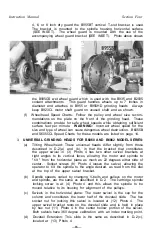
1. To effect manual table traverse, engage the transmission as follows:
(a) B300 Series —The transmission is shipped with gears in neutral
position. To engage direct drive, turn and push in the handwheel
(24) Photo 4 until spring loaded ball is felt dropping into a groove on
the transmission shaft. To shift to low ratio, pull the handwheel out.
As the shaft and handwheel move out of the neutral groove, the low
ratio groove will be felt. Handwheel, shaft, and pinion are positioned
relative to the gear rack by the ball riding in a groove on the shaft.
— 9 -


