


PCIe/PXIe-5211 |
| 46
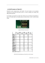
4.3.7 Two-Pulse Encoder
The count value increases on the rising edge of A signal and decreases on the rising
edge of B signal. Default, the A signal must be connected to Counter A terminal, the
B signal mest be connected to Counter B terminal.
Set JY5211CITask.Type to CIType.TwoPulseEncoder to use this function
Timing
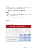
1) Single Mode
The count value is written to the register on each rising edge of the A signal, and B
signel, as shown in Figure 41.
Figure 41 Two-Pulse Encoder in Single Mode
To configure the counter to work in this mode, set JY5211CITask.Mode to
CIMode.Single.
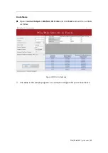
2) Finite/Continuous Mode with Explicit Sample Clock
The count value is stored into the buffer on each rising edge of the sample clock, as
shown in Figure 42.
Summary of Contents for PCIe-5211
Page 9: ...PCIe PXIe 5211 jytek com 5 2 2 Digital IO Specifications Table 1 Digital IO Specifications...
Page 11: ...PCIe PXIe 5211 jytek com 7 2 4 Other Specifications Table 3 Other Specifications...
Page 12: ...PCIe PXIe 5211 jytek com 8 2 5 Front Panel and Pin Definition Figure 3 Front Pannel...
Page 13: ...PCIe PXIe 5211 jytek com 9 Table 4 Pin Defination...
Page 36: ...PCIe PXIe 5211 jytek com 32 Figure 24 Frequency Measure Values In Single Mode...