


PCIe/PXIe-5211 |
| 19
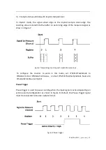
JY5211CITask.EdgeCounting.InputTerminal – Signal-to-measure input terminal.
JY5211CITask.EdgeCounting.Pause.Terminal – Pause signal input terminal.
JY5211CITask.EdgeCounting.DirTerminal – External direction control signal input
terminal.
JY5211CITask.EdgeCounting.OutEvent.Terminal – Count event output terminal.
Learn by Examples 4.3.1
Connect the signal source’s positive terminal Ch1 of a signal source to
PCIe/PXIe-5211 counter0’s edge counting source (CTR0_Source, Pin#65),
negative terminal to the ground (GND, Pin#66) as shown in
Table 2-15 Pin
Defination
. (CTR0_Source, GND) consists of an edge counting counter input.
Set the signal source Ch1’s output to squarewave signal (f=1Hz,
�
�
=3.3v,
�
�
=0v).
Single Mode
Open
Counter Input-->Winform CI Single EdgeCounter
, set the following
numbers as shown:
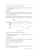
Figure 10 Edge Counting In Single Mode
Count direction
is set by
Direction.
The table in the sample program is a connection diagram for your convenience.
Click
Start
, and the result is shown by
Count
. In this example
Count
increases by
1 every second for a 1Hz squarewave.
Summary of Contents for PCIe-5211
Page 9: ...PCIe PXIe 5211 jytek com 5 2 2 Digital IO Specifications Table 1 Digital IO Specifications...
Page 11: ...PCIe PXIe 5211 jytek com 7 2 4 Other Specifications Table 3 Other Specifications...
Page 12: ...PCIe PXIe 5211 jytek com 8 2 5 Front Panel and Pin Definition Figure 3 Front Pannel...
Page 13: ...PCIe PXIe 5211 jytek com 9 Table 4 Pin Defination...
Page 36: ...PCIe PXIe 5211 jytek com 32 Figure 24 Frequency Measure Values In Single Mode...